


o
Clock LED
Connect the Clock LED
cathode
to the nearest digital ground connection. Connect to
the cathode one quarter to a half inch from the rear of the LED. Make sure you the
LED doesn’t get too hot. Snip off any excess cathode lead length. Don’t connect
anything to the anode yet.
o
Random Reference LED
Connect the Random Reference LED
cathode
to the nearest digital ground
connection. Connect to the cathode one quarter to a half inch from the rear of the
LED. Make sure you the LED doesn’t get too hot. Snip off any excess cathode lead
length. Don’t connect anything to the anode yet.
o
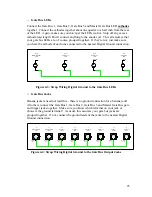
Random Reference and Random Signal Level Pots
Back
of
Pot
Back
of
Pot
R17
Random Reference
100K Linear
R18
Random Level
100K Linear
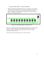
Figure 4-5: Strap Wiring Digital Ground to the Random Control Pots
Connect the ground lug of the Random Reference and Random Signal Level pots to
digital ground. Remember, you’re in the bizarro world of the rear panel, so the
ground lug is to your right, as you’re looking at the panel.
o
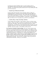
Clock Input Jack, External Load Jack and Random Input Jack
Banana jackers need not apply. For all others, connect the ground lug of the Clock
Input Jack, External Load Jack and Random Input Jack to each other or the nearest
Digital Ground point on the panel.
o
8X2/16X1 and Random/Pattern Mode Switches
Connect together either the upper or lower terminals on the rear of these two mode
switches (remember, do not apply any strapping to the Invert B switch!). If they’re
not close to each other, just connect them to the nearest Digital Ground point on the
panel. Being the SPST ON-OFF type, like the pattern switches, they don’t really
“care” which terminal you connect to, just as long as you have it oriented correctly
26