


6.
Installing the Panel/PCB Connection Wiring
The Final Panel Assembly Step
This chapter of the
electro-music
Klee Sequencer Build Instruction finishes up all of the
major panel work, which, as mentioned before, is where the real work in building the
Klee Sequencer truly is.
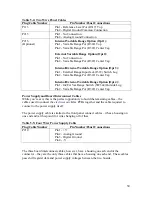
For Those Not Using the Plugs and Headers
If you have decided to wire up the panel with point-to-point wiring, eschewing the use of
headers, etc, this chapter will serve as your guide where to solder the wires to the Klee
PCBs. As it’s covered in the cable assembly chapter, which you probably didn’t read
because you don’t intend to build cables, the plug numbers (P numbers) will tell you
where on which board to solder the wires. However, this information has been added to
the wiring diagrams – below the plug number is the connector number (J) and the board
on which the connector is located. Remember, on the boards, pin 1 for each connector is
a square pad, and the pin numbers count sequentially from there.
Wiring Diagrams
The wiring diagrams assume that the panel has already been strap wired. Some
connections may not jibe directly as illustrated with what you have already strap wired –
for example, you may have strap wired to the top rear terminal of an SPST ON-OFF
switch as opposed to the bottom – don’t worry about those differences. As described
earlier in the panel mounting section, which terminal is connected on those switches
doesn’t matter, as long as the switch is oriented in the right direction in relation to the
panel legend.
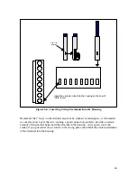
The illustrations cover each plug separately – you can follow through with each
illustration and wire them up accordingly. Pay very close attention to the plug pin
numbering as opposed to what you’re wiring up – things aren’t all that sequential, so
don’t get caught up in assuming they are!
It is a very good idea to label your plug/ housings once the cable is wired to the panel.
You will thank yourself profusely later if you do that now. There are so many of them,
when the time comes to plug everything into the boards, you will find yourself having to
trace through the connections to see which plug is which. Use a sharpie or some other
method to mark the plugs “P208”, “P105”, etc. In fact, mark both sides of them so they
can be identified from any angle.
53