


Grnd” and Digital Ground is labeled “Digital Grnd”. The Bus 1 and Bus 3 connections
appear on page 3 of that schematic. There are a few “sundry” connections that can be
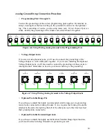
made at this point as well – the connection from the Clock Input Jack to the Clock Enable
Switch, for example, or if used, the connection between the External Load Input Jack and
the optional External Load Enable Switch.
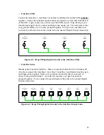
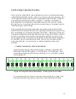
By far, the most extensive common connection is Digital Ground – the pattern switches,
merge switches, mode switches (with the exception of Invert B), step and load switches,
all LEDs, random input jack, reference and level pots, and gate bus jacks all connect to
this point. It’s a busy little ground!
Analog ground is used for all of the programming pots, the optional external range
components (if used) and all of the voltage output jacks.
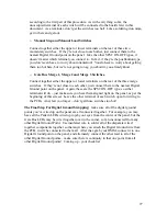
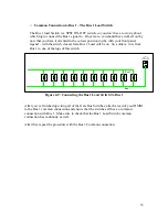
Bus 1 connects to either the upper or lower terminal (depending on your panel labeling)
of all of the gate bus switches AND the Bus 1 Load Switch.
Bus 3 connects to either the upper or lower terminal (depending on your panel labeling)
of all of the gate bus switches.
There are a few components that don’t require any strap wiring at all – notably, the rotary
Range Switch and the Invert B switch. And, of course, if you are using banana jacks,
there are no common ground inputs for any of the jacks.
This build document provides procedures for the strap connections so that you can go
through them, and, in the end, determine if you have made all of your strap connections
and are ready to move on with your life. In fact, here they come now!
23