


o
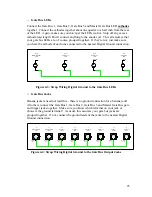
Gate Bus LEDs
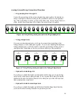
Connect the Gate Bus 1, Gate Bus 2, Gate Bus 3 and Master Gate Bus LED
cathodes
together. Connect the cathodes together about one quarter to a half inch from the rear
of the LED. Again, make sure you don’t get the LEDs too hot. Snip off any excess
cathode lead length. Don’t connect anything to the anodes yet. This all assumes that
your gate bus LEDs are, of course, grouped together. If they’re not, just make sure
you have the cathode of each one connected to the nearest Digital Ground connection.
D17
Gate Bus 1
LED
D18
Gate Bus 2
LED
Anode
Cathode
Anode
Cathode
Anode
Cathode
Anode
Cathode
D19
Gate Bus 3
LED
D20
Master Gate Bus
LED
Figure 4-3: Strap Wiring Digital Ground to the Gate Bus LEDs
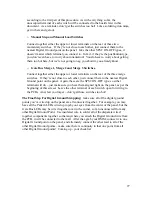
o
Gate Bus Jacks
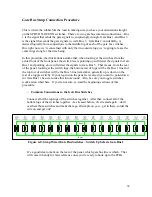
Banana jackers need not read this – there is no ground connection for a banana jack!
All others, connect the Gate Bus 1, Gate Bus 2, Gate Bus 3 and Master Gate Bus gate
and trigger jacks together. Make sure you know which terminal on your jack of
choice is the ground terminal! As usual, this assumes your gate bus jacks are
grouped together. If not, connect the ground leads of the jacks to the nearest Digital
Ground connection.
J1
Gate Bus 1
Gate
J2
Gate Bus 1
Trigger
J3
Gate Bus 2
Gate
J4
Gate Bus 2
Trigger
J5
Gate Bus 3
Gate
J6
Gate Bus 3
Trigger
J7
Master Gate Bus
Trigger
J8
Master Gate Bus
Gate
Ground
Lug
Ground
Lug
Ground
Lug
Ground
Lug
Ground
Lug
Ground
Lug
Ground
Lug
Ground
Lug
Figure 4-4: Strap Wiring Digital Ground to the Gate Bus Output Jacks
25