V&T Technologies Co., Ltd.
http://www.ecodrivecn.com
Chapter 6 Parameter Description
64
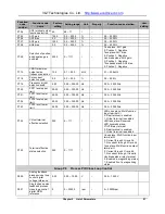
physical parameter. The adjustment result will be added to the open loop frequency reference of the
inverter, so as to ensure the constancy of the physical parameter through speed control. Refer to the
description of the open loop and closed loop composite operation relation calculation parameter P1.08.
Vector control 2 without encoder speed feedback:
4: Process open loop control: Applicable to high performance applications and features high rotation
speed precision, high torque precision and eliminates the need for pulse encoder.
5: Analog value feedback process close loop control: Refer to Parameter setting 1 of this function code.
6: Single-phase pulse process close loop control: Refer to Parameter setting 2 of this function code.
7: Composite control: For the composite control of process open loop and analog feedback closed loop,
refer to parameter setting 3 of this function code
Note: V5-H series only support vector control 2 without encoder speed feedback, if vector control 2 with
encoder speed feedback is needed, please select V6-H series product.
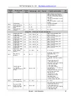
This function is applicable to the frequency reference of open loop control mode, such as vector control 1,
vector control 2. For the speed reference of process close loop control mode, refer to function code of
Group P1.
0: Set frequency reference via P0.05.
Note: If multi-section digital voltage terminals 1 ~ 3 are valid, the frequency is determined by the terminal
combination. Refer to P4.15
~
P4.21. If multi-section frequency terminals 1 ~ 4 are valid, the frequency is
determined by the terminal combination. Refer to P4.22
~
P4.36.
1: Set frequency reference via AI1 port.
2: Set frequency reference via AI2 port.
Input specification of AI1 and AI2 terminals: 0~10V or 0~20mA. The correspondence relation between
the analog and the reference frequency is defined by group P6.
Note: When adopting the current input of 0~20mA, refer to the description of P6.01~P6.08.
3: Set frequency reference via AI3 port.
Input specification of AI3 terminal: -10~10V. The correspondence relation between the analog absolute
value and the reference frequency is defined by group P6. The operation direction is determined by the
sign of the AI3 analog input.
4: Set frequency reference via X7/DI port.
X7/DI terminal input specification: 0~maximum pulse frequency P5.10. The correspondence relation
between the pulse signal and the reference frequency is defined by group P6.
Note: When P0.04=4, the X7/DI terminal function must be set to pulse frequency DI input (P5.06=5) .
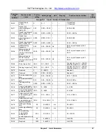
Three different operating command reference modes can be selected for the inverter.
0: Operation panel mode: Perform the Run, Stop, Forward/reverse operation of the inverter through the
RUN, STOP/RST, FWD/REV buttons of the operation panel.
1: Terminal mode: Perform the Run, Stop, Forward/reverse operation of the inverter by defining the
P0.04
Open loop main reference mode
0~4(0)
P0.05
Open loop digital frequency reference
0.00
~
300.00 Hz
(
50.00Hz
)
P0.06
Running command reference mode
0~2(0)


