V&T Technologies Co., Ltd.
http://www.ecodrivecn.com
Chapter 6 Parameter Description
94
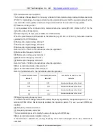
will be limited to 0V automatically.
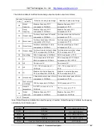
This function code determines the maximum frequency output by the terminal Y2/DO. Refer to P7.01 for
details.
This function can be used for load change detection. Once the output terminal is set to “22: Zero Current
Detection Arrival”, indication signal will be output upon the inverter output current is lower than the zero
current detection width P7.18.
Note: This function parameter is percentage of the inverter output current to rated current of the motor.
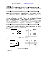
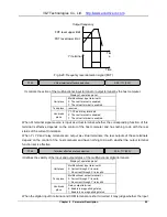
This function is used for detecting the deviation between output frequency and setup frequency. Once
the output terminal function is set to “1: Frequency Arrival Signal”, the deviation between the output
frequency and the setup frequency of the inverter is in the setup range of this function code and
indication signal is output, as shown in Fig.6-28 Frequency Arrival Signal FAR.
Yi represents Y1 terminal, Y2 terminal or relay terminal.
Output Frequency
Setup Frequency
Detection Width
Time
Time
Yi Terminal
Output Frequency
Setup Frequency
Detection Width
Time
Time
Yi Terminal
Fig.6-28: Frequency arrival signal (FAR)
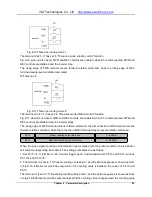
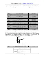
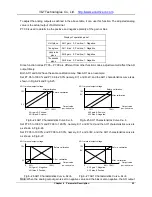
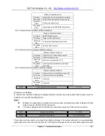
This function is used for detecting whether the output frequency in within the setup FDT. The output
terminal function is set to “2: Frequency level detection signal 1” or “3: Frequency level detection signal
2”, the output frequency is in the corresponding FDT setup range and indication signal is output.
P7.10
Y2/DO Maximum output pulse frequency
0.1~50.0 kHz(10.0kHz)
P7.18
Zero current detection width
0.0~ 50.0 %(0.0%)
P7.19
Frequency arrival detection width
0.00 ~ 300.00 Hz(2.5Hz)
P7.20
FDT1 level upper limit
0.00 ~ 300.00 Hz(50.00Hz)
FDT1 level lower limit
0.00 ~300.00 Hz(49.00Hz)
P7.22
FDT2 level upper limit
0.00 ~ 300.00 Hz(25.0Hz)
P7.23
FDT2 level lower limit
0.00 ~ 300.00 Hz(24.00Hz)
P7.21


