V&T Technologies Co., Ltd.
http://www.ecodrivecn.com
Chapter 3 Wiring of Inverter
19
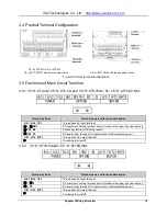
3.4 Product Terminal Configuration
V5
−
H
−2T0.4G~V
5
−
H
−2T2.2G
V5
−
H
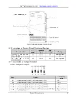
−4T7.5G/11L and below power class
V5
−
H
−4T11G/15L and above power class
Fig.3
−
2 Product terminal configuration
3.5 Functions of Main Circuit Terminal
3.5.1 V5
−
H
−2T0.4G
~V5
−
H
−2T2.2G and V
5
−
H
−4T0.75G/1.5L
~V5
−
H
−4T15G/18.5L
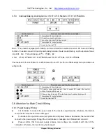
3.5.2 V5
−
H
−4T18.5G/22L~V
5
−
H
−4T75G/90L
Terminal symbol
Terminal name and function description
R/L1, S/L2, T/L3
Three-phase AC input terminal
⊕
1,
⊕
2/B1
DC reactor connecting terminal, short circuited with copper bus upon delivery
⊕
2/B1, B2
Connecting terminal of braking resistor
⊕
2/B1,
Ө
DC power input terminal; DC input terminal of external braking unit
U/T1, V/T2, W/T3
Three-phase AC output terminal
Grounding terminal PE
Terminal symbol
Terminal name and function description
R/L1, S/L2, T/L3
Three-phase AC input terminal
⊕
1,
⊕
2
DC reactor connecting terminal, short circuited with copper bus upon delivery
⊕
2,
Ө
DC power input terminal; DC input terminal of external braking unit
U/T1, V/T2, W/T3
Three-phase AC output terminal
Grounding terminal PE


