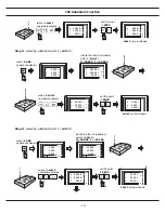
2.3 LINEAR TRANSDUCER CONNECTION
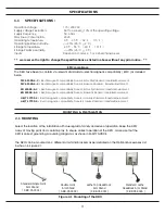
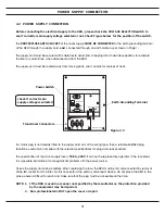
Connection sockets as shown in Figure 2.3. The transducers are connected to the DRO with 9-pin DB
Type connectors.
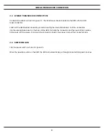
Switch off the DRO before connecting or disconnecting the linear transducers. To fit the connectors
into the appropriate socket on the back of the DRO, first align the connector and then push firmly in place.
And secure with the screws. To remove the connectors, loosen the screws and pull the connector clear.
2.4 SWITCHING ON
Find the power switch as shown in Figure 2.3.
When the operators switch on the DRO, the DRO will automatically go through a brief self diagnostic routine.
IV
LINEAR TRANSDUCER CONNECTION
Содержание ES-12
Страница 1: ...Always Committed to Quality Technology Innovation ES 12 Digital Readout System Operation Manual...
Страница 8: ...1 Basic Fucntions Basic Functions BASIC...
Страница 15: ...8 Built in Calculator Calculator...
Страница 27: ...20 REF datum memory...
Страница 31: ...24 LHOLE tool positioning for the Line Holes...
Страница 35: ...28 INCL Inclined angle tool positioning...
Страница 40: ...33 PCD tool positioning for Pitch Circle Diameter...
Страница 45: ...R R R 38 tool positioning for ARC machining...
Страница 63: ...R R R 56 Simplified R function...
Страница 73: ...66 Shrinkage Calculation L L X 1 005...
Страница 91: ...Parameter Setup B 1 SET UP...


