background image

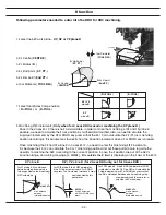
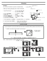
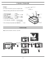
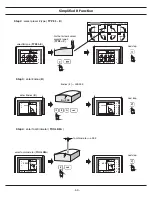
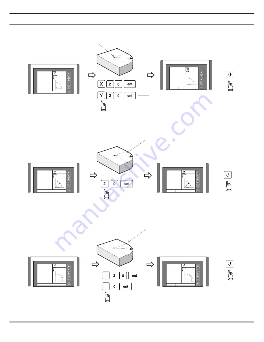
R function - XY plane ARC

- 52 -

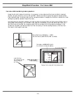
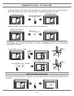
x

Y

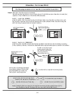
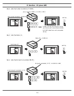
Step 4 : enter the Start point's coordinate ( 

ST. PT

 )

centre coordinate ( CENTRE ) : X=20.000, Y=20.000

enter centre's coordinate ( XY CENTRE )

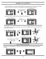
next step

next step

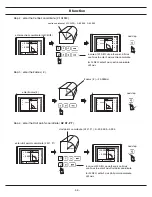
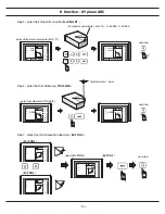
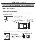
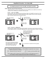
Step 2 : enter the Centre's coordinate ( XY CENTR )

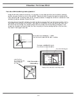
in case of 2X DRO, since there is no Z axis
use Y axis to enter Z axis centre coordinate

for 3X DRO, enter Z axis centre coordinate
at Z axis

next step

Step 3 : enter the Radius ( R )

enter Radius ( R )

Radius ( R ) = 20.000mm

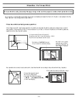
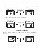
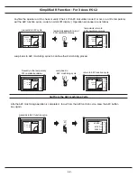
start point's coordinate ( ST. PT ) : X=20.000, Y=0.000

enter start point's coordinate ( ST. PT )

R

X
Y
Z

INC

R FUNC

 CENTER

Y

X

R

0.000

0.000

CENTER

X
Y
Z

INC

R FUNC

 CENTER

Y

X

R

20.000
20.000

CENTER

X
Y
Z

INC

R FUNC

Rad i us?

Y

X

R

0.000

Radius

X
Y
Z

INC

R FUNC

Rad i us?

Y

X

R

20.000

Radius

X
Y
Z

INC

R FUNC

XY ST. POINT

Y

X

R

0.000
0.000

R ST. POINT

X
Y
Z

INC

R FUNC

XY ST. POINT

Y

X

R

20.000

0.000

R ST. POINT

Содержание ES-12

Страница 1: ...Always Committed to Quality Technology Innovation ES 12 Digital Readout System Operation Manual...

Страница 2: ...ified R Function 56 10 Shrinkage Calculation Function 66 11 Lathe Application Supplement A 1 12 Parameters Setup B 1 13 Scale Installation Manual C 1 Safety Notice Installation I Specifications II II...

Страница 3: ...n Do not disassemble the display by yourself if there is any fault ask the professional for help to repair it If you dismantle it by yourself it may cause electric shock or fire Make sure the plug is...

Страница 4: ...l Shock The DRO s grounding to the earth terminal of a power socket source which protected by an Earth Leakage Circuit Breaker must be connected Install the Power Grounding as per shown in following d...

Страница 5: ...and brackets as per detailed on the Optional Accessories List As shown in Figure 2 1 Figure 2 1 Mounting of the DRO II SPECIFICATIONS MOUNTING INSTALLATION The DRO have been to conforms to relevant st...

Страница 6: ...e EARTHED plug should be used which complies with the relevant specifications for plugs and socket outlets The specification of the mains supply fuse is T0 5A 220V It can not be replaced by operator I...

Страница 7: ...fit the connectors into the appropriate socket on the back of the DRO first align the connector and then push firmly in place And secure with the screws To remove the connectors loosen the screws and...

Страница 8: ...1 Basic Fucntions Basic Functions BASIC...

Страница 9: ...swap to Metric display Inch Metric display conversion X Y Z X Y Z ABS ABS mm mm mm mm mm mm 12 345 25 000 25 000 0 000 X Y Z ABS mm mm mm 1 0000 2 0000 3 0000 X Y Z ABS mm mm mm 1 0000 2 0000 3 0000 X...

Страница 10: ...k piece Step 1 Locate the edge finder at one end of the work piece then zero the X axis Step 2 Located the edge finder at the opposite end of the work piece X Y Z ABS mm mm mm 0 000 0 000 0 000 X Y Z...

Страница 11: ...axis in INC coordinate for any relative position machining The work piece datum work piece ZERO position is still keep in ABS coordinate of the DRO Operator can switchs between ABS absolute and INC in...

Страница 12: ...ed rate in CNC machining or cutting tool feed calculations SPEED function is very useful in monitoring many common machining process such as cutting facing and etc to achieve predictable surface finis...

Страница 13: ...ncel any vibration filtering to get the most sensitive and fastest response position display to make the manual machine positioning more comfortable to operate When the machine is moving by the power...

Страница 14: ...xample To get the summing display of X and Z axes the same operation if we want summing the Y and Z axes if we want YZ summing just replacing the X axis button key press with Y axis button key press a...

Страница 15: ...8 Built in Calculator Calculator...

Страница 16: ...orignal coordinate before the result transfer the operator can contiinue the remaining machining as normal The built in calculator offers following advantages 1 Operations are same as normal commeric...

Страница 17: ...76 mm mm mm 12 345 78 975 45 765 X Y Z ABS 76 mm mm mm 12 345 78 975 45 765 10 Built in Calculator Example To enter into calculator function i e Trigonometric calculation COS 100 X COS 30 86 602540 Th...

Страница 18: ...e machine to X display 0 000 then the tool is located at the position of X 108 675 Tool is now at the position of calculated result X 108 675 in the above example press the CE key to return to the nor...

Страница 19: ...12 199 Subdatum Function sdm 1 Subdatum 1 sdm 3 Subdatum 3 sdm 4 Subdatum 4 ABS work piece datum sdm 2 Subdatum 2...

Страница 20: ...any change in ABS datum zero point However all sdm coordinates are relative to ABS coordinate all sdms position are relative to ABS s zero it will shift together with ABS zero position changes 2 All s...

Страница 21: ...50 50 35 sdm 2 Subdatum 2 X Y Method 1 move the machine to required subdatum position then ZERO SdM display coordinate Set up the work piece datum in ABS coordinate then move the machine to required...

Страница 22: ...witch to ABS coordinate display switch to ABS coordinate display locate the tool at subdatum point 3 sdm 3 X 50 000 Y 50 000 locate the tool at subdatum point 2 sdm 2 X 50 000 Y 50 000 X Y Z SDM 1 mm...

Страница 23: ...an press or to directly switch to the required subdatum sdm coordinate The DRO s XY displays is now switched to refered to ABS zeros The DRO s XY displays is now switched to refered to sdm 1 zeros swi...

Страница 24: ...ero is a much more quicker more efficient and less mistake method Method 2 direct keyin the sdm zero position coordinate coordinate relative to ABS zero set this point to ZERO switch to ABS coordinate...

Страница 25: ...when the coordinated is entered into the DRO the displayed coordinate in the axis display shows a negative sign of your entered coordinate It is correct because your tool is now loacted at the ABS zer...

Страница 26: ...plays is now switched to refered to sdm 1 zeros switch to next UP sdm coordinate display Example switch to next DOWN sdm coordinate display switch to next UP sdm coordinate display The DRO s XY displa...

Страница 27: ...20 REF datum memory...

Страница 28: ...work piece datum ABS zero position in the DRO s memory Then in case of power failure happen after recovery from the power failure we can use the REF datum memory function to re install the store relat...

Страница 29: ...e accident happen You are for sure the work datum will never losted Step 3 move the machine across the center of the glass grating scale until the X axis digit display start run please notice that the...

Страница 30: ...ABS coordinate it can enter into the ref function FIND REF find REF mark RECALL 0 recall work zero to select the RECFALL 0 find REF mark select X Y Z or U axis U or to select all axes respectively sel...

Страница 31: ...24 LHOLE tool positioning for the Line Holes...

Страница 32: ...unction will temporarily preset all Line Holes position 0 000 0 000 operator can press or keys to select the Line Holes and move the machine to display 0 000 0 000 then the Line Holes position is reac...

Страница 33: ...e angle LIN ANG enter Line distance LIN DIST all LHOLE machining parameters to enter into the LHOLE machining mode already entered into the DRO operator can press or to select the Line Hole s number t...

Страница 34: ...porarily swap to normal XYZ coordinate display swap back to LHOLE function cycle swap back to LHOLE function cycle to continue the Line Holes machining operation After the Line Holes machining operati...

Страница 35: ...28 INCL Inclined angle tool positioning...

Страница 36: ...thod It is very time consuming ES 12 provides an very easy to use INCL function to help the operator to posit the tool along an inclined angle For lathe application since the lathe have very different...

Страница 37: ...ect work plane or XY plane XZ plane YZ plane select XY plane as the work plane Inclined angle INCL ANG 20 degree counter clockwise enter incline angle INCL ANG press to enter into the INCL machining f...

Страница 38: ...he inclined axis A ZERO the dial imdicator at one end of the work piece after move the machine to Y axis display 0 000 then Y axis position is accuractely posited at the 20 degree operator can fine tu...

Страница 39: ...emporarily swap to normal XYZ coordinate display swap back to INCL function cycle swap back to INCL machining mode display continue the INCL machining operation After the INCL machining operation comp...

Страница 40: ...33 PCD tool positioning for Pitch Circle Diameter...

Страница 41: ...ckwise End angle End ANG 300 degree clockwise after the above machining parameters are entered into the DRO the PCD function will temporarily preset all Pitch Holes position 0 000 0 000 operator can p...

Страница 42: ...Holes NO HOLE 5 Start angle ST ANG 30 degree 80 000 enter the CENTRE coordinate centre coordinate CENTRE X 0 000 Y 0 000 Step 2 Enter the Centre coordinate CENTRE next step 1 2 3 4 5 X Y Z ABS CENTER...

Страница 43: ...PCD machining mode already entered into the DRO operator can press or to select the Pitch Hole s number and move the machine to display 0 000 then the Pitch Hole position is reached 2 1 1 4 5 3 1 3 2...

Страница 44: ...D function cycle temporarily swap to normal XYZ coordinate display swap back to PCD function cycle swap back to PCD function cycle to continue the PCD machining operation After all Pitch Holes machini...

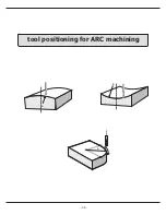
Страница 45: ...R R R 38 tool positioning for ARC machining...

Страница 46: ...r to have your work piece to be machined in a CNC mcachine please bear in mind that ARC function is only cost effective and time saving under following conditions tool positioning for ARC machining 1...

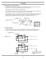
Страница 47: ...the lead screw dial direction are as follows therefore DRO s display direction are also normally be set to the direction as per follows NOTICE Coordinate have signs to specify it s relative location f...

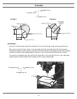
Страница 48: ...n calculate all the ARC tool positions on XZ YZ work plane and assist the operator to posit the tool to the ARC machining points by a simulated Z position the simulated Z position is showed on the mes...

Страница 49: ...WN key is pressed When machining the XZ and YZ plane R in 3 axes ES 12 no need to enter this Machining STEP increments it is because the ES 12 can calculate the X or Y machining positions and set thos...

Страница 50: ...mpensation R TOOL Actual ARC Radius R Tool Radius 8 Z increment per step Z STEP 0 3mm for 2 Axes DRO only No Need for 3 Axes DRO In case 2 Axes ES 12 is used we must first reset the Z Dial to simulate...

Страница 51: ...here is no Z axis use Y axis to enter Z axis centre coordinate for 3X DRO enter Z axis centre coordinate at Z axis next step Step 3 enter the Radius R enter Radius R Radius R 20 000mm start point s co...

Страница 52: ...ate XZ ENd P next step enter start point s coordinate XZ ENd P Tool Diameter 6mm Step 7 select tool compensation direction R TOOL R TOOL R TOOL select R TOOL next step R TOOL X Y Z INC R FUNC XZ END P...

Страница 53: ...ion and perset the X axis in case XZ plane R or Y axis in case of YZ plane R to 0 000 to guide the operator to machine the ARC profile In this example XZ plane R is selected therefore move the X axis...

Страница 54: ...resently in the temporarily XYZ coordinate display swap back to ARC machining cycle return to ARC function cycle Afte the ARC machining operation is completed to quit from the ARC function cycle press...

Страница 55: ...CUT entered enter Z step increment Z STEP Z Axis increment per step machining is fixed Z STEP 0 3mm The DRO wil calculate the best Z step increment so that the Max distance between each machining poin...

Страница 56: ...th the tool posited at the starting point of the ARC then press UP or DOWN key once to simulate Z axis move up or down the Z axis for one step the corresponding Z dial turn number and Z dial reading w...

Страница 57: ...nytime during the ARC machining currently Z STEP increment 0 3mm change the Z STEP change Z STEP increment 0 5mm now the Z STEP increment 0 5mm R 0 3 R 0 5 Afte the ARC machining operation is complete...

Страница 58: ...iameter TOOL DIA 6 000 mm 7 Tool Compensation R TOOL Actual ARC Radius R Tool Radius 8 Max cut between interpolated points MAX CUT 0 3mm MAX CUT 0 3 mm Tool diameter 6mm End point 40 20 Centre 20 20 D...

Страница 59: ...r 3X DRO enter Z axis centre coordinate at Z axis next step Step 3 enter the Radius R enter Radius R Radius R 20 000mm start point s coordinate ST PT X 20 000 Y 0 000 enter start point s coordinate ST...

Страница 60: ...meter 6mm Step 7 select tool compensation direction R TOOL R TOOL R TOOL select R TOOL next step R TOOL X Y Z INC R FUNC XY END POINT Y X R 0 000 0 000 R END POINT X Y Z INC R FUNC XY END POINT Y X R...

Страница 61: ...ints along the ARC curvature then move the machine to XY displays 0 000 0 000 to arrive at the curvature position move the machine to XY displays 0 000 0 000 move the machine to XY displays 0 000 0 00...

Страница 62: ...ocess Presently in the temporarily XYZ coordinate display swap back to ARC machining cycle return to ARC function cycle Afte the ARC machining operation is completed to quit from the ARC function cycl...

Страница 63: ...R R R 56 Simplified R function...

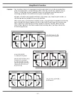
Страница 64: ...ery short time After a work survey we found that in majority of cases only eight type of simple ARC are normally used in the ARC machining Therefore this ES 12 have built in those 8 types of commonly...

Страница 65: ...UP or DOWN key is pressed When machining the XZ and YZ plane R in 3 axes ES 12 no need to enter this Machining STEP increments it is because the DRO can calculate the X or Y machining positions and se...

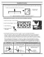
Страница 66: ...machining into two parts Second Part Use the Preset R Type 3 First Part Use the Preset R Type 2 posit the tool at the ARC start point surface of the work piece centre in this case set the Z dial to ZE...

Страница 67: ...pe TYPE 1 8 Radius R 200 000 next step enter Radius R R 200 Step 3 enter Radius R next step Tool Diameter 6 000 enter Tool diameter TOOL DIA X Y INC SIM R R type 1 8 0 X Y INC SIM R R type 1 8 2 X Y Z...

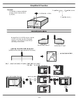
Страница 68: ...three axes ARC machining operation the ES 12 will calculate the ARC profile according to the current Z axis position and perset the X axis in case XZ plane R or Y axis in case of YZ plane R to 0 000 t...

Страница 69: ...ily XYZ coordinate display swap back to ARC machining cycle return to ARC function cycle Afte the ARC machining operation is completed to quit from the ARC function cycle press the ARC buttion key aga...

Страница 70: ...the MAX CUT entered enter Z step increment Z STEP Z Axis increment per step machining is fixed Z STEP 0 3mm The DRO wil calculate the best Z step increment so that the Max distance between each machi...

Страница 71: ...ting point of the ARC then press UP or DOWN key once to simulate Z axis move up or down the Z axis for one step the corresponding Z dial turn number and Z dial reading will display on the unused axis...

Страница 72: ...s choosed in the R MODE menu of SETUP the Z STEP increment can be changed anytime during the ARC machining currently Z STEP increment 0 3mm change the Z STEP change Z STEP increment 0 5mm now the Z ST...

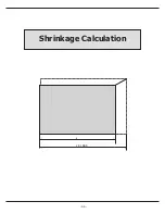
Страница 73: ...66 Shrinkage Calculation L L X 1 005...

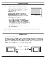
Страница 74: ...o make mistake it is a very heavy psychological stress to the operator 3 If any mistake happen it is quite a big cost to fix especially after the mould hardened ES 12 provides a practical Shrinkage ca...

Страница 75: ...in the drawings Shrinkage calculation KEYs for expand calculation for reduce calculation Example To calculate the expaned dimension of current X axis displayed dimension 27mm expanded 27 1 005 26 886...

Страница 76: ...To compensate by Reduce so that the DRO s actual displayed dimension are reduced by the ratio of the shrink factor When the ES 12 is in Shrinkage Compensation display mode the displayed dimensions in...

Страница 77: ...sation mode display press to return to normal dimenson display currently in shrinkage compensation display return to normal display normal actual dimension display X Y Z ABS SHRINK mm mm mm 100 500 10...

Страница 78: ...s to enter the shrink factor 2 Set the ES 12 to Expand Compensation mode for machining 1 Enter the Shrink Factor into the ES 12 in this example the ABS plastic is used of which the shrink factor is 1...

Страница 79: ...nk compensation mode display for further machining Expand Actual Dimension display Shrinkage Compensated display The displayed dimension are now divided by the shrink factor 1 005 in this example Duri...

Страница 80: ...tary chapter of the manual is only valid for the setting of DRO TYPE LATHE in the SETUP menu This is an supplementary chapter to the normal operation manual it gives more realistic operational example...

Страница 81: ...difficult mission for us when we design the summing function of this DRO is different people have different practise some of them want to put the longitudinal axis in the X axis display display but s...

Страница 82: ...t all in order to keep the X axis position right at the cutting position of making this first slight cut c Measure the work piece by a caliper i e The measured diameter of the work piece is 45 80mm d...

Страница 83: ...e tool tips offset so that the operator don t have to datum the tool tips position whenever tool change is made Example 2 Currently in TOOL 3 display coordinate to switch to TOOL 9 display coordinate...

Страница 84: ...ample To accuractely swing the tool turret on the cross slide by 20 degree so that the operator can make to conical machining as per following diagram shown Angular direction positive clockwise negati...

Страница 85: ...ncline angle INCL ANG The DRO is now entered into the INCL machining function cycle The swinging of the lathe s tool turret on the cross slide to an inclined angle of 20 degrees accurately is an itera...

Страница 86: ...ocated at the inclined axis Y0 Y0 Step 5 move the tool turret to a distance let s take an example of 50mm as per shown in following digram calculate the Y axis Z axis travel by the COS angle of the mo...

Страница 87: ...ely process operator may have to repeat the Step 4 to Step 8 again to fine tune the incline angle until there is no swinging of the tool turret is needed in the Step 8 which means the best possible al...

Страница 88: ...ed work piece This DRO offers cone measuerment function for the ease of cone angle measuerment to help the operator to obtain a accurate and faster conical process For example to verify the conical wo...

Страница 89: ...remind the operator that the axis display zero position is preset to Y TAN ANG operator simply move the machine to X 0 000 then the tool is accurately located at the inclined axis Y0 Y0 0 05mm since...

Страница 90: ...te display swap back to INCL function cycle swap back to INCL machining mode display continue the cone measurement operation After the INCL machining operation completed press to exit from the INCL fu...

Страница 91: ...Parameter Setup B 1 SET UP...

Страница 92: ...function 3 After entered in the reset function ES 12 will process a RAM TEST to test all RAM memory and also reset all RAM memory to 0 Finally resume all factory default setting 4 Reset completed the...

Страница 93: ...machine application 4 EDM EDM machine application 5 CS LATHE Constant Linear Speed Lathe machine application To make the ES 12 more user friendly the display message can be configured to one of the fo...

Страница 94: ...ecifies the Z axis interoplation method during the ARC or R function This ES 12 can offer MAX CUT or Z STEP for choices If MAX CUT selected the ARC or R function calculation will interoplated the ARC...

Страница 95: ...nto the SETUP function 1 Switch off the ES 12 2 Switch on the ES 12 after switching on with the software version no VER X in the message window press ent key to enter the parameter SETUP function 2 Pr...

Страница 96: ...unctions function availiable in this DRO TYPE not available Every 100mm per length specification mill EDM grinder lathe CS LATHE DRO TYPE Functions Built in Calculator PCD pitch circle diameter LHOLE...

Страница 97: ...select the LANGUAGE displays Select GERMAN message display Select CHINESE message display Select ITALIAN message display Select SPANISH message display Select ENGLISH message display Select CZECH mes...

Страница 98: ...ay at all or the DRO functions not work properly ES 12 displays AXIS NO means DRO have entered into the AXIS NO selection menu user must specify the correct no of axes exists in the DRO so that all re...

Страница 99: ...s to select the DIRECTN selection menu DIRECTN menu is designed to allow user to swap the transducer linear scale or encoder counting direction The count direction of the transducer are specified by 0...

Страница 100: ...olution display for each individual axis The ES 12 is design to work with the linear scales of either 0 005mm or 0 001mm resolution Mixed resolutions display i e X axis in 0 005mm Y axis in 0 001mm re...

Страница 101: ...2X display If the axis display is configured as DIA display a d character will be displayed at the first digit display of the axis to have the user easily recongise the display is in DIA mode All DRO...

Страница 102: ...grade higher such as 0 001mm resolution and 0 01mm in accuracy 2 The error must be recoded in metric unit um micron 0 001mm e g we measure the X axis and record an display error of 19um shorter over...

Страница 103: ...s CPU then compensat the readout readings according to the error table that built during this SETUP process The compensation always started at the error curve start position as per the digram below I...

Страница 104: ...real time compensation calculation possible the DRO assume all internal error compensation calculation are only in positive direction Therefore the CP START position should be always located in the mo...

Страница 105: ...n in this example the CP START position 115 875 3 START measure the error to build up a error curve To mark the error measurement more easy swap to INC coordinate and zero at the CP START position swa...

Страница 106: ...in press the ent to enter to SETUP function During the start up procedure when the DRO display the Version No VER X press ent once to enter to the SETUP function after entered into SETUP function pres...

Страница 107: ...xis measured values are to be input enter the MEAS VAL of each measurement step press UP or DOWN button to scoll through all measurement steps X axis measured value Y axis measured value Y X ent ent e...

Страница 108: ...up Procedure NL ERROR after all measured values entered into the DRO press ent to exit the NL ERROR function Non Linear Error Compensation Value input completed selection done go to next menu B 18 X Y...

Страница 109: ...C or R machining function For three axes ES 12 this parameter Z DIAL is not used no effectiveness For Example The Z Dial is the Z axis machine movement per Dial turn e g The Z movement per dial turn i...

Страница 110: ...g function For three axes ES 12 this parameter DIAL INC is not used no effectiveness For Example Press to select the DIAL INC selection menu The Z movement per line mark of the Z Dial is displayed on...

Страница 111: ...the Z axis machine increment per line mark of the Z Dial For three axes DRO this parameter R MODE is not used no effectiveness Z STEP MAX CUT The ARC or R function of this DRO have following two metho...

Страница 112: ...arameters Setup Procedure R MODE select the R MODE used MAX CUT used Z STEP used selection done go to next menu B 22 X Y Z U R MODE Z STEP X Y Z U R MODE X Y Z U R MODE Z STEP or X Y Z U R MODE MAX CU...

Страница 113: ...e notice that the vibration filter won t affect the accuracy of the counting The measurement accuracy is the same with or without the filter DRO displays FLTR PR means DRO have entered into the FLTR P...

Страница 114: ...ible the scale ends and the reader head should be installed on a flat surface 3 If a lever dial indicator is used to align the scale it is important to ensure that the angle between the dial Indicator...

Страница 115: ...il Water dust or other foreign products Covers provided should be installed 3 In cases where machined flat surfaces are not available an installation block or strip should be used to provide a flat da...

Страница 116: ...rred and cleaned 6 All cables must be fixed but allow for the maximum machine travel movements Below are diagrams recommending the minium radius that should be used for bending the scale cable 7 Groun...

Страница 117: ...e mounting surfaces are perpendicular to each other I e As per shown in figure c the squareness of these two mounting surfaces must be less than 0 1mm 2 Scale Alignment It is very important that the s...

Страница 118: ...supplied should be placed over the scale for maximum protection Between the scale and the reader head there is a blue strip which helps to maintain the correct distance between the reader head and th...

Страница 119: ...insure that it is parallel and in line with the scales The blue packing between the reader head and scale allows for the correct clearance and holds the reader head parallel to the scale Mount the co...

Страница 120: ...ds the spindle and away from the spindle Fig 1 The bracket is Fig 2 mounted of the knee and around the scale to allow for the cover Fig 3 to protect the scale where excessive coolant swart are present...

Страница 121: ...n be done by either a dial indicator or a precision level When mounting the reader head if necessary pack the reader head so that it travels in line and square to the scale to avoid any damage to the...

Страница 122: ...148 L 128 L 108 7 3 _ 0 25 54 6 _ 0 25 12 3 _ 0 25 28 35 _ 0 25 8 00 21 90 20 50 10 00 80 00 73 00 5 00 9 00 13 00 22 00 16 00 12 00 21 90 33 00 16 95 27 75 19 4 22 50 33 15 50 6 00 2 X M5 0 Gs10 Ser...

Отзывы: