


0
.8
~
1
.5
m
m
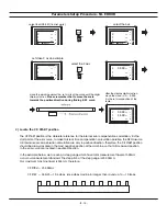
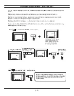
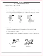
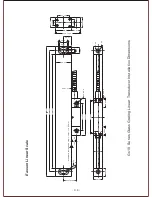
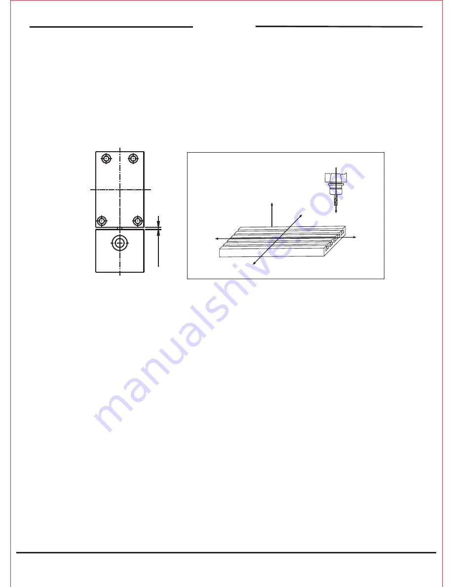
3. Clearances between the reader head and scale body:
Direction on Lathe Installation
(1) The clearance between the reader head and scale body must be kept between 0.8mm-1.5mm.
(2) The reader head must be less than 0.5mm parallel with the scale and can be set with feeler gauges
to allow the reader head to move unrestricted along the scale.
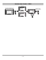
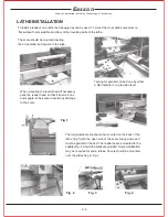
When travelling towards the headstock the reading should be reduced. Cross slide towards the centre
should be reduced.
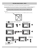
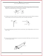
Note!
At all times to give the best protection the scale should be mounted with the rubber seals facing
down.
Where extreme exposure to swarf, coolant, dirt and compressed air, are present, sheet metal cover
guards that are supplied should be placed over the scale for maximum protection. Between the scale
and the reader head there is a blue strip which helps to maintain the correct distance between the reader
head and the scale. This should be removed after installation
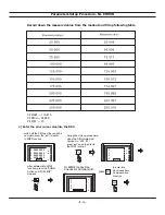
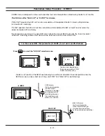
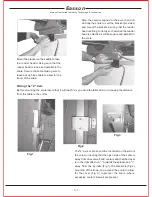
Scale Reading Direction
Before fitting the scale insure that the reading direction is correct. To change the direction of the reading
of the scale, turn the scale over. Generally the scale is reading in the correct direction with the label
of the scale exposed.
Lathe Scale Installation
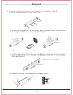
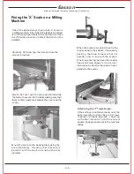
Before fitting the scale connect the "x" axis to the cross slide to allow the Diameter function to work.
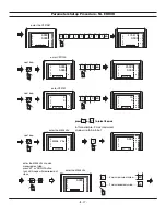
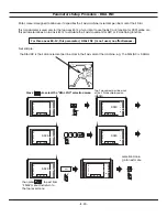
Milling Machine Table Direction
The diagram below shows reading against table travel
Z+
Spindle travel
Table Travel
Z read minus
Y read minus
Y read minus
Y read plus
X read plus
_
Z
Always Committed to Quality Technology & Innovation
Easson
- C. 5 -
Содержание ES-12
Страница 1: ...Always Committed to Quality Technology Innovation ES 12 Digital Readout System Operation Manual...
Страница 8: ...1 Basic Fucntions Basic Functions BASIC...
Страница 15: ...8 Built in Calculator Calculator...
Страница 27: ...20 REF datum memory...
Страница 31: ...24 LHOLE tool positioning for the Line Holes...
Страница 35: ...28 INCL Inclined angle tool positioning...
Страница 40: ...33 PCD tool positioning for Pitch Circle Diameter...
Страница 45: ...R R R 38 tool positioning for ARC machining...
Страница 63: ...R R R 56 Simplified R function...
Страница 73: ...66 Shrinkage Calculation L L X 1 005...
Страница 91: ...Parameter Setup B 1 SET UP...