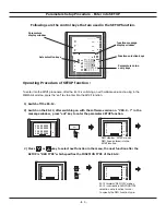


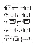

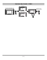
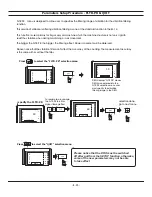

Parameters Setup Procedure - NL ERROR
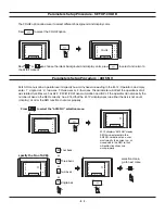
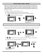
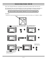
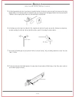
Using a dial indicator to locate the most negative position of the step guage, zero the dial indicator at this position,
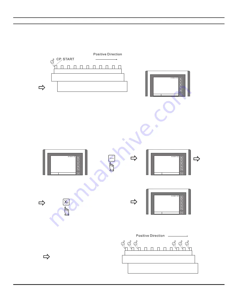
record down this position as the CP. START position.
Because the CP. START position
always at the most negative position
of the machine, therefore, it should
always a NEGATIVE value
Please record down this position
by pen, in this example, the
CP. START position = - 115.875
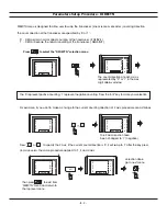
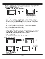
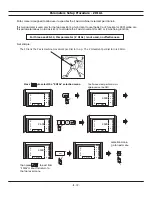
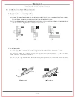
3 ) START measure the error, to build up a error curve
To mark the error measurement more easy, swap to INC coordinate and zero at the CP. START position
swap to INC coordinate
abs
inc
zero the INC coordinate
at CP. START position
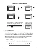
start measure the error by
positioning the dial indicator
on the step guage. Take down
the display value that shown
at the DRO axis display
- B. 15 -
X
Y
Z
ABS
mm
mm
mm
-115.875
2.500
4.750
X
Y
Z
ABS
mm
mm
mm
-115.875
2.500
4.750
X
Y
Z
INC
mm
mm
mm
-115.875
2.500
4.750
X
Y
Z
INC
mm
mm
mm
0.000
2.500
4.750
Содержание ES-12
Страница 1: ...Always Committed to Quality Technology Innovation ES 12 Digital Readout System Operation Manual...
Страница 8: ...1 Basic Fucntions Basic Functions BASIC...
Страница 15: ...8 Built in Calculator Calculator...
Страница 27: ...20 REF datum memory...
Страница 31: ...24 LHOLE tool positioning for the Line Holes...
Страница 35: ...28 INCL Inclined angle tool positioning...
Страница 40: ...33 PCD tool positioning for Pitch Circle Diameter...
Страница 45: ...R R R 38 tool positioning for ARC machining...
Страница 63: ...R R R 56 Simplified R function...
Страница 73: ...66 Shrinkage Calculation L L X 1 005...
Страница 91: ...Parameter Setup B 1 SET UP...