


26
MicroController Control System
Systems Operation
through 5 shield wires(RD, WH, GN, YL, BK).
The logics will start to perform a set of “Run Time”
diagnostic checks. The letter “EE” will flash on the
CVMS display indicating the key is ON with no
operator in the seat.
When the seat switch is closed, current will flow
from the logic DD-2 through the seat switch to logic
DE-5.
And the seat switch is also connected to hourmeter
positive to run the hourmeter.
When the key switch is closed, the battery is used to
power the fan to prevent from overheating controllers.
With the power supplied the logics continues its
checks for any “Run Time” faults. If no faults are
detected the display will indicate the battery charge
level, the power steering(IDLE) system operates, the
pump and drive power circuits receive battery
voltage and the logics receives battery voltage from
BATT + terminal.
Hydraulic Pump Circuit
Only one hydraulic pump motor (series winding) is
used for all power steering, lift, tilt and auxiliary
hydraulic functions. To activate the pump circuit, the
seat switch, key switch and line contactor must be
closed first as explained in the topic, Actuation
Circuit.
Power Steering Circuit
The power steering (PS) circuit has speeds
(PS idle and PS boost-up) independent of the lifting
speeds.
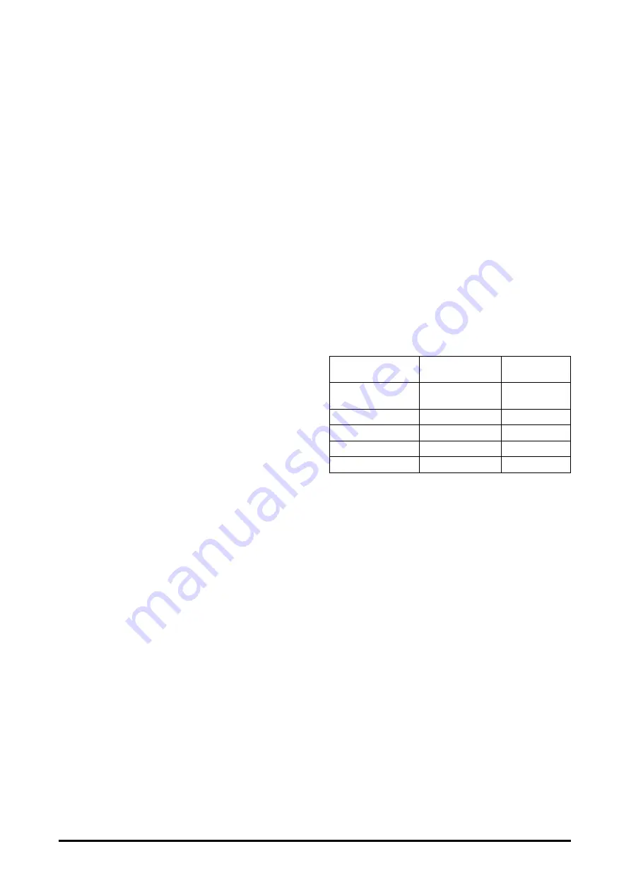
Followings are standard TP pulsing rates of the
signal at the logics.
The above pulsing rate can be adjustable in
“Parameter Setting Menu.”
NOTE:
The circuit diagrams have shaded lines for
illustration of current flow in each circuit.
Other circuits can be activated at the same
time, but each one is shown separately to
illustrate current flow in each individual circuit.
Motor
Speed
TP Pulsing
Rate
Connection
NO.
IDLE &
POWER STEERING
4.8% + compensation
-
TILT
16% + compensation
PE - 5
LIFT
PC - 1
AUX1
60% + compensation
PE - 3
AUX2
60% + compensation
PE - 2
Содержание B20S-3
Страница 3: ......