background image

62

www.digiop.com

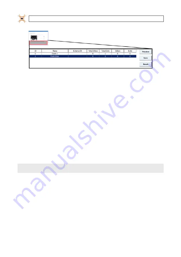
Zone List Box with New Zone renamed

6. 

Complete the normal process for drawing count lines.

5.16  Deleting Enter, Exit, Exclusion Lines, and Filter Zones

Complete the following steps if you want to delete a count line that is attached to a specific zone:

1. 

Access the Counting tab.

2. 

Verify that the Display All check box is not selected.

3. 

Click the reporting zone to which the line or filter zone is attached. All lines and filter zones for the selected zone appear.

4. 

Click the line or filter zone to be deleted. Square handles appear on each end of the line.

5. 

Press the 

Delete

 key to remove the line.


NOTE

The Backspace key does not delete count lines. Use only the Delete key.

6. 

Click 

Save

 to save your changes.

5.17  Deleting Zones and All Attached Count Lines

Complete the following steps if you want to delete a reporting zone and all count lines that are attached to it:

1. 

Access the Counting tab.

2. 

Verify that the 

Display All

 check box is not selected.

3. 

Click the name of the reporting zone to be removed. The selected zone is highlighted.

SECTION 5: CONFIGURE COUNTING LINES

Содержание D3D-2500

Страница 1: ...D Camera User Manual Product D3D 2500 Please read this manual before using your camera and always follow the instructions for safety and proper use Save this manual for future reference DO_D3D 2500_CM...

Страница 2: ...recording of video and or audio signals of others without their knowledge and or consent We encourage you to check and comply with all applicable local state and federal laws and regulations before en...

Страница 3: ...communications Operation of this equipment in a residential area is likely to cause harmful interference in which case the user will be required to correct the interference at personal expense Europea...

Страница 4: ...ess 9 2 1 1 Manually Set a Static IP Address onYour PC 9 2 1 2 Connect the DIGIOP 3D camera to your PC 12 2 1 3 Set the IP Address of the DIGIOP 3D camera 12 2 2 Mount the DIGIOP 3D camera 14 2 3 Conn...

Страница 5: ...iple Count Zone Support 44 5 9 Naming Reporting Zones 45 5 10 Drawing Enter Exit and Exclusion lines 45 5 11 Adding Filter Zones to Count Zones 50 5 11 1 How does a Filter Zone work 50 5 11 2 Using Fi...

Страница 6: ...6 3 Verifying queue placement and camera calibration 81 6 3 1 Types of Maps 81 6 3 2 Verifying queue zone placement usingTraffic and Dwell maps 81 6 3 3 Verifying queueTail placement using Start Stop...

Страница 7: ...GIOP ELEMENTS 101 11 1 Configure DIGIOP 3D camera data streaming 101 11 2 Add the DIGIOP 3D camera to DIGIOP ELEMENTS 103 11 3 Display DIGIOP 3D camera data in DIGIOP Connect 105 SECTION 12 Importing...

Страница 8: ...viii www digiop com...

Страница 9: ...ELEMENTS platform provides a very powerful counting solution with video verification Features include Stereoscopic camera design 3D 5 fps CIF resolution B W video with 2 0 lux Provides queue and serv...

Страница 10: ...ngs and has an IP address of 192 168 1 7 This LED is also used with the manual reset button for more information see Using the Manual Reset Button The normal startup sequence is as follows 1 All LEDs...

Страница 11: ...camera Most pages in the DIGIOP 3D camera Configuration Application have Save Preview Reset and Default buttons The DIGIOP 3D camera has two methods to store configuration information Camera RAM Temp...

Страница 12: ...ppropriate for the mounting height and mounting angle The DIGIOP 3D camera can fully see people unobstructed in both lenses The counting lines are positioned so that a person is tracked for a minimum...

Страница 13: ...e methods of filtering out unwanted objects to prevent them from being counted and or tracked 1 Defined Tracking Range Prevents objects or parts of objects from being tracked based on minimum and maxi...

Страница 14: ...acking Basic sub tab If the object is less than the height specified in the height filter or the object matches the basic shape model for a shopping cart the camera does not count the object However i...

Страница 15: ...ct Because most people are generally within one height range 100 cm 80 cm and most other objects balloons ladders products etc are above 180 cm By default the camera is configured to filter out any ob...

Страница 16: ...OP 3D camera encounters a person carrying a balloon The calculated average mass height of the person is within the acceptable range so the person is eligible for counting The balloon exceeds the maxim...

Страница 17: ...ess for your camera 2 1 1 Manually Set a Static IP Address on Your PC Before connecting the DIGIOP 3D camera to power or to your PC you must first set the IP address on your PC As a best practice DIGI...

Страница 18: ...ON TypicalWindowsXPControlPanel 5 Double click Network Connections The Network Connections window will open TypicalWindowsXPNetworkConnectionswindow 6 Double click Local Area Connection The Local Area...

Страница 19: ...The Internet Protocol TCP IP Properties dialog box appears InternetProtocol TCP IP Propertiesdialogbox 8 Record the current settings in this window so that you can change them back after you set the n...

Страница 20: ...witch to a power outlet 2 Plug an Ethernet CAT5e cable from the In port outside port of the DIGIOP 3D camera to the Network port of the PoE injector or switch 3 Plug an Ethernet drop cable from the Sw...

Страница 21: ...tronglyrecommendsthatyouDONOTUSEDHCPtoconfigureyourcamera UsestaticIPaddressingonly 3 Enter the Network Mask Default Gateway and DNS Server optional addresses for the network where your camera will be...

Страница 22: ...or mounting the camera 7 Complete the steps in this section for each additional DIGIOP 3D camera being installed 8 Set the network configuration of your PC back to its original settings 2 2 Mount the...

Страница 23: ...the camera is looking straight down if possible The DIGIOP 3D camera software also supports mounting at angles in sites where 90 degree downward looking mounting is not possible additional license req...

Страница 24: ...ith Power over Ethernet PoE on 802 3af standards PoE allows for a combined power and network connection using a standard CAT 5 Ethernet cable This section describes how to connect the DIGIOP 3D camera...

Страница 25: ...INSTALLATION 2 3 1 Connect using an end span PoE switch The following diagram show how the camera should be connected to an end span PoE switch Ethernet End span Switch Data Data and Power DIGIOP 3D C...

Страница 26: ...The following diagram shows how DIGIOP equipment should be connected when using a Power over Ethernet Injector Ethernet Switch PoE Injector Data Data Data and Power DIGIOP 3D Camera PoEInjectorimplem...

Страница 27: ...IGIOP 3D camera should be connected when using a multi port mid span PoE injector Ethernet Switch Mid span PoE Injector Data Data and Power DIGIOP 3D Cameras Mid spanPoEinjectorimplementation NOTE Aft...

Страница 28: ...tion options shown in Section 4 Connect Power over Ethernet PoE System at the Site 2 Connect a computer to the same network as the DIGIOP 3D camera 3 Open a web browser and type the IP Address of the...

Страница 29: ...matchtheSiteIDtoasiteIDintheOperationalDatabasetoauto registerthe cameratoasite 3 Click Save 3 3 Set the Date Time Options Setting the time in a DIGIOP 3D camera requires connecting to the time server...

Страница 30: ...will set the camera time to UTC time therefore the time server can be running in any time zone 7 Enter the Port number from which the DIGIOP 3D camera should attempt to get a time synchronization NOTE...

Страница 31: ...ly set the time on the D3D 2500 camera 1 Click Date and Time Info 2 Enter the current date in the Date field 3 Enter the current time in the Time field 4 Click Set Time to set the time on the device t...

Страница 32: ...tab allows you to automatically send aggregated daily metric data to an email account Files are sent in SXML format Complete the following steps to configure the email delivery 1 Access the DIGIOP 3D...

Страница 33: ...check box to activate the Email Delivery fields 6 Enter the recipient s email address in the Recipient field 7 Enter the sender s email address in the Sender field NOTE BoththeRecipientandSenderfieldm...

Страница 34: ...metricdataforeach1minute 5minute 15minute 30minute or60minutetimeperiodovertheprevious24hours Forcounting ifyouselectdaily theemailwill containasingleenterandexitcountfortheprevious24hourperiod 14 Typ...

Страница 35: ...l Files are sent in XML or pipe delimited format When FTP delivery is selected the DIGIOP 3D camera attempts to use the passive FTP protocol If the delivery fails the device then attempts to use activ...

Страница 36: ...28 www digiop com SECTION 3 CONFIGURE THE DIGIOP 3D CAMERA DataDeliveryoptions 4 Click FTP Delivery to expand the FTP Delivery section...

Страница 37: ...29 DIGIOP 3D Camera User Manual SECTION 3 CONFIGURE THE DIGIOP 3D CAMERA FTPDelivery expanded 5 Click the Enable FTP Delivery check box to activate the FTP functionality...

Страница 38: ...tings tab IP Settings sub tab D Inserts the Date of the data contained in the sent data file formatted YYMMDD T Inserts the Time of the last data bucket included in the sent data file formatted HHMMSS...

Страница 39: ...m number of times the camera should attempt to reconnect to the FTP server to send the files when a failure occurs If the Maximum Retries field is set to zero the camera will continue to retry indefin...

Страница 40: ...camera parameters to achieve optimum performance levels 4 1 Calibration Page Overview Calibrationpage Feature Description Image group Show height Displays the height of objects as they are tracked th...

Страница 41: ...acking page To enable the radio buttons you must access the Tracking page http IP Address tracking html and change the Quality values back to the default values Dynamic Range 20 Noise Threshold 75 and...

Страница 42: ...ion DIGIOP recommends that you attempt auto calibration before manually setting the height and rotation values Complete the following steps to perform automatic calibration 1 Access the DIGIOP 3D came...

Страница 43: ...Height X Rotation and Y Rotation 5 Inspect the height and rotation numbers to ensure that they meet the following guidelines Calculated height should be within 20 of visual height estimate X and Y rot...

Страница 44: ...tom Corrective Action Red Blue Increase X Blue Red Decrease X Left Right Corrective Action Blue Red Increase Y Red Blue Decrease Y Acceptable calibration Reason The majority of the floor area is shade...

Страница 45: ...justment Decrease X axis value Reason The top of the floor area is shaded blue the bottom is shaded red and green Increase Y Axis Value Reason The left floor area is shaded blue the right area is shad...

Страница 46: ...djustments or the height is zero click Calculate to retry the calibration procedure If calibration numbers seem inaccurate again or you can not adjust the green box for the floor select the Preview Mo...

Страница 47: ...y the calibration using this procedure 4 4 Setting Object Filtering Options The Calibration tab also contains track filtering options These options allow you to configure the DIGIOP 3D camera to elimi...

Страница 48: ...cts to be part of the normal background environment This adaptation happens more quickly for counting applications than for queueing service and tracking applications NOTE Ifyouhaveaccessedthetracking...

Страница 49: ...image on the left a matching circle should be displayed for them in the right image Observe the actual video stream displayed in the left image space and the 3 D stream displayed in the right image sp...

Страница 50: ...xit lines can be configured to count traffic in any single direction If you want to count people traveling in two directions you must create both an Enter and an Exit line You can also create a pass l...

Страница 51: ...ce of one another Start Track Max Distance Once tracks pass this set of checks they must also stay within a certain distance of one another Track Max Distance through the DIGIOP 3D camera field of vie...

Страница 52: ...ic These tracks are shoppers who are taking the shortest distance to their destination and who are not actually shopping the corner store therefore they should not be included in the enter exit counts...

Страница 53: ...le Enter count The same is true with Exit counts 5 9 Naming Reporting Zones When you configure the DIGIOP 3D camera you should also give the report zone a descriptive name so that you know what area i...

Страница 54: ...ne with enter or exit lines Make sure that the directional circle on the enter or exit line is turned in the direction of traffic flow To draw counting lines 1 Access the DIGIOP 3D camera Configuratio...

Страница 55: ...ID will be sent with the XML packet so that you can map the count data based on your specific needs 7 Click the Enter button in the button bar and draw an enter line on the left image WARNING TheDIGI...

Страница 56: ...Enter and Exit lines in any direction to count traffic flows in various environments Enter green andExit blue lineswithtrafficflowindicators WARNING Ifyoudrawtwoexit orenter linesinsuchawaythattheycou...

Страница 57: ...behindoneanotherhavenoeffectonthe resultingcountsandshouldnotbedrawn Ifyouneedtomovetheline1pixelatatime clickthelinetoselectit thenusethearrowkeysonyourkeyboardtomovethe line Acceptable use of enter...

Страница 58: ...es help you to eliminate false counts from employees customers and doors If you are installing the DIGIOP 3D camera in an environment where the following traffic patterns occur you should configure a...

Страница 59: ...f the filter zone and tracks leaving the store can end before making it to the filter zone Both of the tracks in this sample would not be counted CountingZoneswithaFilterZone badconfiguration Examples...

Страница 60: ...ntrance setting reverses the filter zone logic so that tracks that end in a filter zone are counted as Entrances and tracks that start in the filter zone are counted as Exits When this option is used...

Страница 61: ...dinbetweenthecountinglinesand thedoor 5 Click the orange filter zone Several small orange squares appear these squares are handles that allow you to resize the filter zone to fit your environment 6 Cl...

Страница 62: ...herwise click Save to save your changes and skip steps 8 11 8 Right click the zone name and select Configure The Counting Config Parameters dialog box appears CountingConfigParametersdialogbox 9 Selec...

Страница 63: ...ting Complete the following steps to set count lines to only count tracks that are typically children those that are below the height filter set on the Calibration page 1 Access the Counting page 2 Ri...

Страница 64: ...ping unit 7 Enter the maximum distance in centimeters that tracks are allowed to drift apart after they are initially considered a shopping unit in the Track Max Distance field If tracks separate they...

Страница 65: ...ect This map is useful for verifying correct calibration settings Dwell Map Shows a color coded heat map that displays the dwell points of all tracks since the last reset Dwell points represent where...

Страница 66: ...acks start and end so that you can place the filter in the correct location Complete the following steps to verify Filter Zone placement 1 Clear the maps by resetting the camera then run the camera fo...

Страница 67: ...colors through the main tracking area are the same or similar color of yellow The main color changes should be toward the edges of the image space If you notice that the color changes appear througho...

Страница 68: ...theHeightvalueontheCalibrationpage IncreasetheHeightvalueontheCalibrationpage DecreasetheXRotationvalueontheCalibrationpage IncreasetheXRotationvalueontheCalibrationpage DecreasetheYRotationvalueonthe...

Страница 69: ...de you can create one zone to count customer entrances and one zone to count passes in front of the store entrance Complete the following steps to add additional zones to the device 1 Access the confi...

Страница 70: ...r zones for the selected zone appear 4 Click the line or filter zone to be deleted Square handles appear on each end of the line 5 Press the Delete key to remove the line NOTE TheBackspacekeydoesnotde...

Страница 71: ...nputs from the GPIO port The GPIO port provides three input output streams in any combination Each input output must have a zone created on the counting page prior to configuring the options on the Da...

Страница 72: ...e used to trigger pulse events 9 Select Enters Exits or both check boxes to specify whether pulse outputs are sent for enter and or exit line events 10 Click Save 11 Connect the external device to the...

Страница 73: ...duration of the pulse that is received NOTE Pulselengthmustbebetween10msand3000ms 8 Enter the After Pulse Delay in milliseconds This value sets the minimum time in between successive pulse alerts 9 C...

Страница 74: ...wait time calculations The Queue count and Head zones have parameters that can be accessed by clicking the Advanced button from the Queuing tab When generating queue metrics the D3D 2500 only consider...

Страница 75: ...pop up from either the people in the head zone or any other people currently included in the queue All people counted in the queue must remain within the Track Distance threshold for a specified amoun...

Страница 76: ...rack starts inside the queue count area In some configurations a queue may extend to the edge of the D3D 2500 coverage area In these situations it is impossible for some tracks to start outside of the...

Страница 77: ...e queue count area green and pink zone Must be within the queue count area for longer than the queue minimum time The first person in the queue count area must be within a specified distance from peop...

Страница 78: ...me The person is also inside the queue count area which means they are being counted as part of the queue assume that the person has passed the count ing constraints and was in the current location fo...

Страница 79: ...metric packet at the aggregation level you selected in the Data Delivery tab Otherwise the wait time is discarded The following drawings show how the D3D 2500 handles various queue wait time scenario...

Страница 80: ...irst person starts outside of the queue count area and continues through the pink queue exit at which point their wait time is sent out in a metric packet If the Debug check box is selected a green do...

Страница 81: ...how the queue tail zone is used to increase the wait time sample size Assume that all individuals in this example passed the counting constraints The first person starts inside of the queue count area...

Страница 82: ...he head zone blue zone drawn where the front of the queue forms The head zone must be drawn large enough to encompass the first 3 or 4 people in the queue The queue count area green and pink zone is d...

Страница 83: ...sexceeds1900 datacollectionstopsuntilthenextday ContactDIGIOP ifyouarecollectingqueueorservice timesinextremelyhightrafficenvironments suchasatconferencesortradeshows 1 Open the D3D 2500 configuration...

Страница 84: ...he name field and left click or press Enter to close edit mode 9 Click anywhere in the newly added queue row to display the queue zone in the image 10 Place your mouse cursor in the middle of the blue...

Страница 85: ...to the area where you want to place your queue count area 14 Click the green and pink queue count zone Several small green squares appear these boxes are handles that allow you to resize the queue co...

Страница 86: ...n Note A total of up to 6 zones of any type counting queuing service and detection can be created in each D3D 2500 camera NOTE Upto6zonesofanytype counting queuing service anddetection canbecreatedine...

Страница 87: ...usion area is used to exclude employee wait times See Queue Exclusion Area on for more information To create a Queue Exclusion area 1 Right click a Queue from the Queuing tab Queues group 2 Select Exc...

Страница 88: ...then re enter and have their wait time merged into the queue wait time or service time See Queue Count Area Constraints Default 30 seconds queue Track Dist The maximum distance that a person entering...

Страница 89: ...ighter the colors the higher the traffic volume This map is useful for positioning queue zones so that all queue traffic is counted Start Stop Map Shows the start green and end red points of all track...

Страница 90: ...two dwell areas exist a small one at the service point and a larger one in the queue area There is usually a distinct break between these two areas Position the queue exit line in the break area 8 Cl...

Страница 91: ...ove the mass of green dots at the back of the queue indicate where tracks started Adjust the Queue Tail to include a majority of these start points 4 Click Save to save the changes 6 3 4 Verifying cal...

Страница 92: ...ppen unevenly from the top to bottom of the image space check the Y rotation on the calibration page If color changes occur unevenly from the left to the right of the image space check the X rotation...

Страница 93: ...85 DIGIOP 3D Camera User Manual SECTION 6 CONFIGURING QUEUING APPLICATIONS DecreasetheY rotationvalueonthe Calibrationpage IncreasetheY rotationvalueonthe Calibrationpage...

Страница 94: ...one constraints The D3D 2500 camera sends data packets that contain the service statistics for the data delivery time window These statistics include the Number of People Served Number of Seconds Occu...

Страница 95: ...behind a counter service desk to assist the customer In these configuration the employee exits the employee area and enters the service area The employee service time should not be counted in the ser...

Страница 96: ...second which is less than the merge time The time outside the zone is merged into service time for the track The service time is reported as 17 seconds 15 seconds inside the zone plus 2 seconds that...

Страница 97: ...ueueandservicezones Ifthenumberofwait servicetimesexceeds1900 datacollectionstopsuntilthenextday ContactDIGIOP ifyouarecollectingqueueorservice timesinextremelyhightrafficenvironments suchasatconferen...

Страница 98: ...w to display the service point zone in the image 10 Place your mouse cursor in the middle of the green service zone and click and drag to move it to the area where you want to place your service point...

Страница 99: ...oint zone in the D3D 2500 field of view NOTE Up to 6 zones of any type counting queuing service and detection can be created in each D3D 2500 unit 15 Continue to Creating a Service Exclusion Area in t...

Страница 100: ...remain in the queue count area or service area before they can be counted in the queue length or service time For queues tracks must meet Track Dist and Track Time thresholds Default 5 seconds queue...

Страница 101: ...the counting constraints is within a queue count area and is eligible to be counted as a part of the queue but is not currently being counted The track is not within the Track Distance threshold of a...

Страница 102: ...s functioning as desired 1 Open the D3D 2500 configuration application using your web browser 2 Click the Queuing tab to open the Queuing page 3 In the Queues or Service Points group click the name of...

Страница 103: ...for a username and password before allowing them to view any of the web pages in the application By default password protection is disabled the username and password are set and password protection e...

Страница 104: ...3Dcameraafteryousave 7 Click Save to save the changes The DIGIOP 3D camera is now password protected The next time anyone attempts to access the application from the browser a login screen will appea...

Страница 105: ...you will need to access a password retrieval page on the DIGIOP 3D camera This will create an encrypted file that you will need to email to support digiop com DIGIOP support will then decode the file...

Страница 106: ...e to the desired save location on your PC and click Save The Download Complete window appears DownloadCompletewindow 4 Click Open Folder to open the folder of the save directory 5 Email the saved file...

Страница 107: ...oftware update from upgrade DIGIOP local and 192 168 1 18 via TFTP Reset Privacy Options Status LED 1 Status LED 2 Status LED 3 Reset button Ethernet Activity LED Ethernet Link LED Complete the follow...

Страница 108: ...on Function Green 2 Resets the DIGIOP 3D camera network configuration to 192 168 1 7 Amber 5 Resets all DIGIOP 3D camera parameters to factory defaults and sets the IP address to 192 168 1 7 Red 8 Dis...

Страница 109: ...video streams from the camera 11 1 Configure DIGIOP 3D camera data streaming To setup data streaming in the camera for DIGIOP ELEMENTS do the following 1 Login to the camera using Microsoft Internet...

Страница 110: ...e Data Streaming checkbox to select it b In the IP Address field enter the IP address of your DIGIOP ELEMENTS NVR hDVR In the example shown above the IP address of the NVR hDVR is 192 168 5 11 c In th...

Страница 111: ...device list on the left click the entry for the video server to highlight it then click the New button New Button Add New IP Camera Video Server DIGIOPControlVideoServerandNew 3 In the Camera menu a O...

Страница 112: ...OP 3D CAMERA WITH DIGIOP ELEMENTS e Click Save 4 In the device list on the left click the entry for the data server to highlight it then click the New button 5 In the Create Item New Stream list click...

Страница 113: ...Port field enter 4000 c Click Save 11 3 Display DIGIOP 3D camera data in DIGIOP Connect 1 Open DIGIOP Connect and login to your DIGIOP ELEMENTS NVR hDVR video server If you do not have an entry for t...

Страница 114: ...Password used to login to the server select the Timezone from the drop down list and the Name of the server d Click Save 2 If you do not have an entry for the data server the DIGIOP 3D camera was add...

Страница 115: ...ur data server the administrative Username and Password used to login to the server and the Name of the server d Click Save 3 In the left frame click the triangle before the data server entry to open...

Страница 116: ...108 www digiop com SECTION 11 USING THE DIGIOP 3D CAMERA WITH DIGIOP ELEMENTS...

Страница 117: ...you want to save the configuration file 6 Enter a file name for the file in the file name field 7 Click Save 12 2 Importing a Configuration File Complete the following steps to import a configuration...

Страница 118: ...f the coverage width Having walls on each side of the coverage area allows us to add coverage because an individual s center of mass can never be completely against the wall In fact it is typically at...

Страница 119: ...ft in Mounting Height m Door Width m 11 0 14 10 3 60 5 1 11 3 15 4 3 70 5 3 11 6 15 10 3 80 5 5 11 9 16 4 3 90 5 7 12 0 17 0 4 00 5 9 12 3 17 6 4 10 6 1 12 6 18 0 4 20 6 3 12 9 18 6 4 30 6 5 13 0 19...

Страница 120: ...below Site Name or Number IP Address Network Mask Default Gateway 2 The time zone for the site is ____________________________ 3 Site observes daylight savings time circle one YES NO 4 IP address of...

Страница 121: ...ra secures to bracket with 2 x 20 thread x 3 8 machine screws Mounting Guidelines Prior to cutting a hole for the recess mount verify that there is hollow ceiling space at least 60 mm deep behind the...

Страница 122: ...attaching the eye bolt and safety cable Mounting Guidelines Camera should be oriented such that the LEDs are toward the store interior and the Ethernet cable is toward the store exterior unless obstr...

Страница 123: ...t 48V External power supply should be a limited power supply certified to IEC EN 60950 1 Power Consumption 4W Weight 0 4 lb 0 2 kg unboxed 0 8 pounds 0 4 kg boxed Emissions Compliance Complies with CE...

Страница 124: ...116 www digiop com...

Отзывы: