


D-Show Profile Guide
64
To use the built-in EQ on a channel, do one of the following:
1
Target the channel by pressing its Select switch.
2
Do any of the following:
• To engage the channel High-Pass Filter, press the HPF
switch in the Encoder Assignment section. Toggle HPF
in/out on each channel by pressing its encoder; adjust
HPF frequency by rotating its encoder.
• To engage the built-in 4-band or 2-band EQ, press the
EQ In switch at the bottom of the ACS Equalizer section.
Using Inserts on Channels
You can use software plug-in inserts or hardware inserts on
any Input Channel or FX Return.
Using Plug-In Inserts on Channels
Plug-Ins are arranged in virtual racks, which allow signals to
be sent to and from each plug-in as if it were an external pro-
cessor. Plug-Ins can be used in two ways: as inserts, or as ef-
fects in a Send/Return arrangement.
Insert
The plug-in is patched in at the insert point on an Input
Channel or FX Return. Each Input Channel may have up to
four plug-in inserts.
Send/Return
Signal is sent to the plug-in over any of the sys-
tem busses (usually an Aux Send) and routed back to an Input
Channel or FX Return.
For more information on using plug-ins in a Send/Return ar-
rangement, see “Using Plug-Ins as a Bus Processors” on
page 154.
Inserting Plug-Ins on Channels
You can insert plug-ins on Input Channels and FX Returns di-
rectly from the Inputs page or from the Plug-In Rack.
To insert a plug-in on a channel:
1
Go to the Inputs page and target the channel where you
want to insert the plug-in.
2
In the Inserts section of the Inputs page, do one of the fol-
lowing:
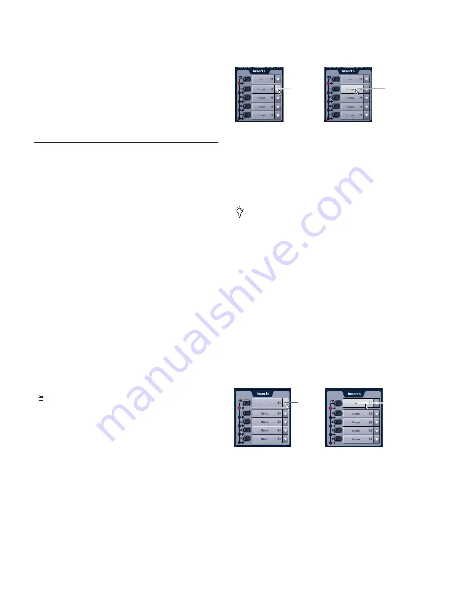
• Click one of the four Plug-In Insert pop-up menus and
choose a plug-in directly from one of the Plug-In Rack
submenus.
– or –
• Click one of the four Plug-In Insert buttons to go to the
Plug-In Rack, and route the signal to the plug-in using
Plug-In Rack controls.
The name of the plug-in insert appears in the on-screen
Plug-In Insert display.
Using Hardware Inserts on Channels
D-Show lets you insert external processors in the signal chain
of Input Channels and FX Returns.
Assigning Hardware Inserts to Inputs
You can assign hardware inserts to Input Channels and FX Re-
turns directly from the Inputs page or from the Patchbay.
To assign a hardware insert to an input:
1
Go to the Inputs page and target the channel where you
want to assign the hardware insert.
2
In the Inserts section of the Inputs page, do one of the fol-
lowing:
• Click the Hardware Insert pop-up menu and choose an
insert destination directly from the menu.
– or –
• Click the Hardware Insert button to go to the Inserts page
of the Patchbay, and assign the insert from the Patchbay.
The name of the hardware insert destination appears in the
on-screen Hardware Insert button.
See Chapter 19, “Plug-Ins.”
Assigning a plug-in insert in the Inputs page
Outputs also provide hardware inserts. For more informa-
tion, see “Using Inserts on Output Busses” on page 72.
Assigning a hardware insert in the Inputs page
Click to
assign
Click to
go to the
Plug-In
Rack
Click to
go to the
Patchbay
Click to
assign
Содержание D-Show Profile
Страница 10: ...D Show Profile Guide x ...
Страница 11: ...Part I Overview and Installation ...
Страница 12: ......
Страница 16: ...D Show Profile Guide 6 ...
Страница 32: ...D Show Profile Guide 22 ...
Страница 33: ...Part II System Description ...
Страница 34: ......
Страница 50: ...D Show Profile Guide 40 ...
Страница 58: ...D Show Profile Guide 48 ...
Страница 67: ...Part III Signal Routing ...
Страница 68: ......
Страница 94: ...D Show Profile Guide 84 ...
Страница 102: ...D Show Profile Guide 92 ...
Страница 110: ...D Show Profile Guide 100 ...
Страница 134: ...D Show Profile Guide 124 ...
Страница 135: ...Part IV Processing ...
Страница 136: ......
Страница 144: ...D Show Profile Guide 134 ...
Страница 171: ...Part V Shows ...
Страница 172: ......
Страница 180: ...D Show Profile Guide 170 ...
Страница 204: ...D Show Profile Guide 194 ...
Страница 227: ...Part VI Specifications ...
Страница 228: ......
Страница 236: ...D Show Profile Guide 226 D Show Output Signal Flow Diagram Version 1 3 07 07 05 ...
Страница 245: ...Part VII Reference ...
Страница 246: ......
Страница 258: ...D Show Profile Guide 248 ...
Страница 269: ......


