background image


3.


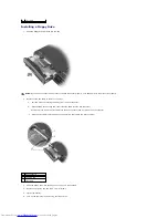
Connect the modem cable to the new modem.  


4.


Align the modem with the screw holes and press the modem into its connector on the system board.  


Install the two M2 x 3-mm screws to secure the modem to the system board. 

5.


Replace the memory module/modem cover and screw:  


a.


Place the memory module/modem cover over the memory module/modem compartment so that the end of the cover with the screw hole is lined 

up with the lines and arrows on the bottom of the computer.  
 

b.


Press down on the center of the memory module/modem cover, and slide the cover until it is secured.  


c.


Replace and tighten the M2.5 x 5-mm screw.  


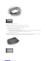
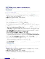
1  M2 x 3-mm screws (2) 

2  pull tab 

3  modem cable connector 

4  modem cable 

NOTICE: 

The cable connectors are keyed for correct insertion; do not force the connections. 

NOTICE: 

Replace the memory module/modem cover so that it is seated properly around the edges and does not bulge near the center of the cover. 

Tightening the memory-module/modem cover screw when the cover is improperly seated can damage your computer. 

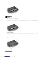
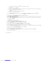
1  M2.5 x 5-mm screw 

2  memory module/modem 

cover 

3  arrows (2) 

4  lines (2) 

Содержание Inspiron 2600

Страница 1: ...ly forbidden Trademarks used in this text Dell the DELL logo Inspiron Dell Precision Dimension OptiPlex and Latitude are trademarks of Dell Computer Corporation Intel Celeron Pentium and Intel SpeedStep are registered trademarks of Intel Corporation Microsoft MS DOS and Windows are registered trademarks of Microsoft Corporation Other trademarks and trade names may be used in this document to refer...

Страница 2: ...thermal pad installed attach a new thermal pad inside the square etching on the MCH heat sink located on the inside of the base plastics Back to Contents Page NOTICE Disconnect the computer and any attached devices from electrical outlets and remove any installed batteries NOTICE To avoid ESD ground yourself by using a wrist grounding strap or by touching an unpainted metal surface on the computer...

Страница 3: ......

Страница 4: ...tem board 12 Remove the M2 x 4 mm screw from the battery latch assembly 13 Remove the latch spring and plate from the bottom case Replacing the Battery Latch Assembly 1 Attach the latch spring to the latch spring connector in the bottom case NOTICE Disconnect the computer and any attached devices from electrical outlets and remove any installed battery NOTICE To avoid ESD ground yourself by using ...

Страница 5: ...w holes are properly aligned To prevent the latch assembly from coming loose apply pressure to the latch plate and spring while replacing the latch button 4 Replace and tighten the M2 x 4 mm screw that secures the latch button to the bottom case Ensure that the newly installed latch moves smoothly and freely when pushed and released Back to Contents Page ...

Страница 6: ... pops up c Remove the battery 10 To dissipate any static electricity while you work use a wrist grounding strap or periodically touch an unpainted metal surface 11 Handle components and cards with care Do not touch the components or contacts on a card Hold a card by its edges or by its metal mounting bracket Hold a component such as a microprocessor by its edges not by its pins CAUTION Only a cert...

Страница 7: ...crew Identification When you are removing and replacing components photocopy Screw Identification as a tool to lay out and keep track of the screws The placemat provides the number of screws and their sizes 1 back 2 right 3 front 4 left NOTICE When reinstalling a screw you must use a screw of the correct diameter and length Ensure that the screw is properly aligned with its corresponding hole and ...

Страница 8: ...d to Bottom Case 4 each Display Assembly to Back Panel 2 each Display Feed Flex Cable to System Board 2 each Hinge Bracket to Bottom Case 4 each Display Bezel 5 each Screw Covers 5 each Display Panel 4 each Display Feed Flex Cable to Display Assembly 1 each Display Latch 2 each EMI Shield 3 each Top of Palm Rest to Bottom Case 2 each ...

Страница 9: ...Video Card to Bottom Case 1 each Palm Rest to Bottom Case 12 each Floppy Drive Cage to Bottom Case 2 each Hard Drive Cage to Bottom Case 2 each System Board to Bottom Case 6 each Battery Latch Assembly to Bottom Case 1 each ...

Страница 10: ...ide the Computer before performing the following procedure NOTICE Do not touch the processor die Press and hold the microprocessor down on the substrate on which the die is mounted while turning the cam screw to prevent intermittent contact between the cam screw and microprocessor NOTICE To avoid damage to the microprocessor hold the screwdriver so that it is perpendicular to the microprocessor wh...

Страница 11: ...ate is complete the computer will automatically reboot 3 Press during POST to enter the system setup program 4 Press to reset the computer defaults 5 Press to save configuration changes and exit the system setup program 6 Remove the flash BIOS update floppy disk or CD from the drive and restart the computer Back to Contents Page NOTICE Ensure that the cam lock is in the fully open position before ...

Страница 12: ...al assistance The diagnostic test groups or subtests also have these helpful features l Options that let you perform quick checks or extensive tests on one or all devices l An option that allows you to choose the number of times a test group or subtest is repeated l The ability to display test results or to save them in a file l Options to temporarily suspend testing if an error is detected or to ...

Страница 13: ...en is presented as follows l On the left side of the screen the Device Groups area lists the diagnostic test groups in the order they will run if you select All from the Run tests menu category Press the up or down arrow key to highlight a test device group l On the right side of the screen the Devices for Highlighted Group area lists the computer s currently detected hardware and some of the rele...

Страница 14: ...in the Parallel Ports tests Back to Contents Page to use them Keys Explains the functions of the all of the keystrokes that can be used in the Dell Diagnostics Device Group Describes the test group that is presently highlighted in the Device Groups area on the main menu screen It also provides reasoning for using some tests Device Describes the function and purpose of the highlighted device in the...

Страница 15: ...CE You must remove the display assembly before you remove the palm rest NOTICE Disconnect the computer and any attached devices from electrical outlets and remove any installed battery NOTICE To avoid ESD ground yourself by using a wrist grounding strap or by touching an unpainted metal surface on the computer NOTICE Read Preparing to Work Inside the Computer before performing the following proced...

Страница 16: ...or to remove the connector from the system board 7 Remove the two M2 5 x 5 mm screws from each hinge block 8 Lift the display assembly up and out of the bottom case 14 1 Inch Display 1 M2 5 x 5 mm screws 4 2 hinge blocks 2 3 M2 5 x 5 mm screws 2 4 display feed flex cable 5 pull tab ...

Страница 17: ...4 display panel 9 flex cable retention bracket 5 M2 5 x 5 mm screws 2 10 top cover NOTICE Disconnect the computer and any attached devices from electrical outlets and remove any installed battery NOTICE To avoid ESD ground yourself by using a wrist grounding strap or by touching an unpainted metal surface on the computer NOTICE Read Preparing to Work Inside the Computer before performing the follo...

Страница 18: ... feed flex cable to the display assembly 7 Unsnap the flex cable retention bracket from the top cover and lift the bracket out of the display assembly 8 Lift the display panel from the top and rotate the display panel out of the top cover 9 Disconnect the bottom flex cable connector from the inverter connector on the system board by pulling on the attached pull tab away from the inverter connector...

Страница 19: ...le of the display feed flex cable to the display panel 4 Place the bottom edge of the display panel in the bottom of the top cover and elevate the top of the panel with your hand 5 Lay the display panel in the top cover 6 Reinstall the four M2 x 3 mm screws that secure the display panel to the top cover 7 Reinstall the M2 5 x 5 mm screw that secures the display feed flex cable to the display assem...

Страница 20: ... panel out of the top cover 9 Disconnect the bottom flex cable connector from the inverter connector on the system board by pulling on the attached pull tab away from the inverter connector 10 Pull the top flex cable connector down and away to remove it from the display panel connector NOTICE Disconnect the computer and any attached devices from electrical outlets and remove any installed battery ...

Страница 21: ...the display bezel 4 Remove the two M2 5 x 5 mm screws that secure the display latch and bracket to the top cover 5 Lift the display latch bracket and spring up and out of the top cover Replacing the Display Latch 1 Attach one end of the spring to the spring hook on the left edge of the display latch and attach the other end of the spring to the spring hook in the top cover 2 Place the display latc...

Страница 22: ......

Страница 23: ...ctions on the screen to continue 3 From the Language pull down menu in the toolbar select your preferred language for the driver or utility if available A welcome screen appears 4 Click Next The CD automatically scans your hardware to detect drivers and utilities used by your computer After the CD completes the hardware scan you can also detect other drivers and utilities Under Search Criteria sel...

Страница 24: ...ollback If you install a new device driver that causes system instability you can use Windows XP Device Driver Rollback to replace the new device driver with the previously installed version of the device driver If you cannot reinstall your previous driver by using Device Driver Rollback then use System Restore to return your operating system to its previous operating state before you installed th...

Страница 25: ...dware Troubleshooter list click I need to resolve a hardware conflict on my computer and then click Next Using Microsoft Windows System Restore The Window XP operating system provides a System Restore feature that allows you to return your computer to an earlier operating state if changes to the computer s hardware or software including new hardware or program installations or other system setting...

Страница 26: ...lick Next If a calendar date has only one restore point then that restore point is automatically selected If two or more restore points are available click the restore point that you want to use 5 Click Next The Restoration Complete screen appears after System Restore finishes collecting data and then the computer automatically restarts 6 After the computer restarts click OK To change the restore ...

Страница 27: ... of the fan cover and pry the cover loose from the bottom case 5 Lift the fan cover up and away from the bottom case 6 Disconnect the fan cable connector from the system board 7 Lift the fan out of the bottom case NOTICE To prevent data loss turn off the computer before removing the back panel fan Do not remove the fan while the computer is on or in a power management mode NOTICE Read Preparing to...

Страница 28: ...om case 2 Tuck the fan cable under the bottom case and connect the cable to the system board 3 Replace the fan cover and reinstall the two M2 5 x 5 mm screws that secure the cover to the bottom case Back to Contents Page 1 fan 2 fan cable connector 1 fan cable ...

Страница 29: ...r CAUTION If you remove the hard drive from the computer when the drive is hot do not touch the metal housing of the hard drive NOTICE To prevent data loss turn off the computer before removing the hard drive Do not remove the hard drive while the computer is on or in a power management mode NOTICE Hard drives are extremely fragile even a slight bump can damage the drive NOTICE Read Preparing to W...

Страница 30: ...4 Use the Operating System CD to install the operating system for your computer 5 Use the Drivers and Utilities CD to install the drivers and utilities for your computer Back to Contents Page ...

Страница 31: ...at blade screwdriver or plastic scribe to lift the scalloped right edge of the center control cover and pry the cover loose from the hinges and bottom case d Lift the center control cover up and away from the hinges and bottom case NOTICE Disconnect the computer and any attached devices from electrical outlets and remove any installed battery NOTICE To avoid ESD ground yourself by using a wrist gr...

Страница 32: ...keyboard connector to disconnect it from the interface connector on the system board 1 scalloped edge of center control cover 2 center control cover 3 display assembly HINT The M2 5 x 4 mm screws are silver 1 M2 5 x 4 mm screws 4 2 scalloped edge of blank key 3 keyboard 4 palm rest NOTICE The keycaps on the keyboard are fragile easily dislodged and time consuming to replace Be careful when removin...

Страница 33: ...he front edge of the keyboard is aligned with the edge of the palm rest before proceeding 4 Check that the keyboard is correctly installed The keys should be flush with the left and right surfaces of the palm rest 5 Replace the four M2 5 x 4 mm screws at the top of the keyboard 6 Replace the center control cover Ensure that the center control cover is snapped in properly so that it is flush with t...

Страница 34: ...ard from the bottom case NOTICE Disconnect the computer and any attached devices from electrical outlets and remove any installed battery NOTICE To avoid ESD ground yourself by using a wrist grounding strap or by touching an unpainted metal surface on the computer NOTICE Read Preparing to Work Inside the Computer before performing the following procedure NOTICE When reconnecting the display feed f...

Страница 35: ...em board and slide the top edge of the video card under the palm rest 2 Lay the video card flat on the system board and connect the video card connector to the interface connector on the system board 1 M2 5 x 5 mm screw 1 2 video card 1 M2 5 x 5 mm screw 1 2 palm rest 3 top right corner of the video card 4 guide ...

Страница 36: ...rd by the pull tab toward the front of the computer to remove the video card from the bottom case 1 bottom of video card 2 video card connector 3 system board 4 interface connector NOTICE Disconnect the computer and any attached devices from electrical outlets and remove any installed battery NOTICE To avoid ESD ground yourself by using a wrist grounding strap or by touching an unpainted metal sur...

Страница 37: ...Lay the video card flat on the system board and connect the video card connector to the interface connector on the system board 1 video card 2 M2 5 x 8 mm screw 1 3 pull tab 1 M2 5 x 8 mm screw 1 2 palm rest 3 top right corner of the video card 4 guide NOTICE Before you connect the video card to the system board ensure that you route the power board flex cable under the memory module ...

Страница 38: ...2 video card connector 3 system board 4 interface connector 5 power board flex cable 6 memory module NOTICE Disconnect the computer and any attached devices from electrical outlets and remove any installed battery NOTICE To avoid ESD ground yourself by using a wrist grounding strap or by touching an unpainted metal surface on the computer NOTICE Read Preparing to Work Inside the Computer before pe...

Страница 39: ...st use your fingers to separate the palm rest from the base plastics by lifting the inside of the palm rest while pushing in on the outside Back to Contents Page 1 M2 5 x 8 mm screws 12 1 back center of the palm rest 2 touch pad connector 3 power board connector NOTICE Carefully separate the palm rest from the base plastics to avoid damage to the palm rest ...

Страница 40: ... Connectors Dell Inspiron 2600 and 2650 USB Connector PS 2 Connector Video Connector Parallel Connector USB Connector PS 2 Connector Video Connector Pin Signal 1 USB5V 2 USBP 3 USBP 4 GND Pin Signal 1 KBDATA 2 PS2DATA 3 GND 4 VCC 5 KBCLK 6 PS2CLK ...

Страница 41: ... 9 5V 2 CRT_G 10 GND 3 CRT_B 11 MONITOR_DETECT 4 NC 12 DDC_DATA 5 GND 13 CRT_HS 6 GND 14 CRT_VS 7 GND 15 DDC_CLK 8 GND Pin Signal Pin Signal 1 STROBE 10 ACK 2 PD0 11 BUSY 3 PD1 12 PE 4 PD2 13 SLCT 5 PD3 14 AFD 3M 6 PD4 15 ERROR 7 PD5 16 INIT 8 PD6 17 SLIN 9 PD7 18 25 GND ...

Страница 42: ... Close the display Press To exit standby mode press the power button or open the display depending on how you set the options on the Advanced tab You cannot make the computer exit standby mode by pressing a key or touching the touch pad Hibernate Mode Hibernate mode conserves power by copying system data to a reserved area on the hard drive and then completely turning off the computer When the com...

Страница 43: ...lp file see Accessing Help for more information on low battery warnings Power Meter Tab The Power Meter tab displays the current power source and amount of battery charge remaining Advanced Tab The Advanced tab allows you to l Set power icon and standby mode password options l Depending on your operating system program the following functions Prompt user for an action Ask me what to do Activate st...

Страница 44: ...K to accept any changes and then click OK to close the Intel SpeedStep window You can also change the Intel SpeedStep settings by right clicking the flag icon in the notification area Battery Performance Battery performance varies depending on operating conditions The operating life of the battery is significantly reduced when you perform operations including but not limited to the following l Usi...

Страница 45: ... System Components Hard Drive Back Panel Fan Inspiron 2650 Only Memory Module Modem Optical Drive and Floppy Drive Keyboard Display Assembly and Display Latch EMI Shield Video Card and Palm Rest Microprocessor Thermal Cooling Assembly Microprocessor Module Speakers System Board Base Plastics Battery Latch Assembly ...

Страница 46: ...hat displays the setting or value for that option You can change settings that appear as white type on the screen Options or values that you cannot change because they are determined by the computer appear less bright A box in the upper right corner of the screen displays help information for the currently highlighted option a box in the lower right corner displays information about the computer S...

Страница 47: ...d then click Display 5 Follow the instructions shown on the screen HINT See the Tell Me How help file for information on standby mode see Accessing Help Check the power light When the power light is lit or blinking the computer has power If the power light is blinking the computer is in standby mode press the power button to exit standby mode If the light is off press the power button to turn on t...

Страница 48: ...nsert a bootable floppy disk or CD Non system disk or disk error A floppy disk is in the floppy drive Remove the floppy disk and restart the computer Operating system not found Contact Dell for technical assistance see Contacting Dell in the Dell Owner s Manual that came with your computer A required DLL file was not found The program that you are trying to open is missing an essential file Remove...

Страница 49: ...lors Screen area and Advanced Settings See Error Messages If an error message appears see Error Messages Connect an external monitor 1 Turn off your computer and connect an external monitor to the computer 2 Turn on the computer and the monitor and adjust the monitor brightness and contrast controls If the external monitor works the computer display or video controller may be defective Contact Del...

Страница 50: ...ct your ISP Check the telephone wall jack Disconnect the telephone line from the modem and connect it to a telephone Listen for a dial tone Ensure that you have touchtone telephone service Try connecting the modem to a different telephone wall jack Slow connection speeds can be caused by telephone noise as well as by telephone line or network conditions Contact your telephone company or network ad...

Страница 51: ...r is unlocked if it has a locking tab or button Reinstall the scanner driver See the scanner documentation for instructions Check the PC Card Ensure that the PC Card is properly inserted into the connector Ensure that the card is recognized by Windows Double click the Safely Remove Hardware Unplug or Eject Hardware in Windows 2000 icon in the Windows taskbar Ensure that the card is listed If you h...

Страница 52: ...top click the Start button point to Programs point to Accessories and click Notepad 5 Type some characters on the integrated keyboard and verify that they appear on the display If the characters appear now but did not with the external keyboard you may have a defective external keyboard Contact Dell see Contacting Dell in the Dell Owner s Manual that came with your computer HINT For information on...

Страница 53: ...artially ejected 3 Gently pull out the tray until it stops l Ensure that the sound is not caused by the program that is running l Ensure that the disk or disc is inserted properly Disable standby mode in Windows before writing to a CD RW See the Tell Me How help file or search for the keyword standby in the Windows XP Help and Support Center Help in Windows 2000 See Accessing Help Change the write...

Страница 54: ...rogram that is no longer responding 3 Click End Task Turn the computer off If the computer does not respond to a keystroke or a proper shutdown press the power button until the computer turns off Press the power button again to restart the computer The solid blue screen appears because you were not able to perform a proper Windows shutdown ScanDisk automatically runs during the start up process Fo...

Страница 55: ...our computer Resolving Other Technical Problems Back to Contents Page HINT See Limited Warranties and Return Policy in the Dell Owner s Manual that came with your computer for information on your warranty coverage Go to the Dell Support website Go to support dell com for help with general usage installation and troubleshooting questions See Dell Technical Support Policy U S Only in the Owner s Man...

Страница 56: ... routing clips and die casting 10 Remove the speakers by pulling them straight up and out of the bottom case NOTICE Disconnect the computer and any attached devices from electrical outlets and remove any installed battery NOTICE To avoid ESD ground yourself by using a wrist grounding strap or by touching an unpainted metal surface on the computer NOTICE Read Preparing to Work Inside the Computer b...

Страница 57: ... connector to the system board Back to Contents Page 1 left speaker 2 right speaker NOTICE Ensure that the speaker cables are under or between their routing clips and route the left and right speaker cables properly beneath the die casting HINT Speakers face out in the bottom case holders HINT The right speaker cable is longer than the left speaker cable ...

Страница 58: ... set Inspiron 2650 Intel 845MZ Inspiron 2600 Intel 830MG Data bus width 64 bits DRAM bus width 64 bits Microprocessor address bus width 32 bits Flash EPROM Inspiron 2650 39F040 512 KB 8 bit data bus Inspiron 2600 28F040 512 KB 8 bit data bus Graphics bus integrated graphics PCI bus standard 32 bit PCI bus PC Card CardBus controller O2 Micro OZ6912 PC Card connector supports one Type I or Type II c...

Страница 59: ... external 4x AGP Inspiron 2600 UMA Video controller Inspiron 2650 NVIDIA GeForce2 Go 100 Inspiron 2600 Intel 830 MG Video memory Inspiron 2650 8 MB or 16 MB external DDR Inspiron 2600 System memory 128 MB System memory 256 MB UMA shared with system memory up to 32 MB UMA shared with system memory up to 48 MB LCD interface SPWG Display Type active matrix TFT XGA Dimensions 14 1 inch or 15 inch Heig...

Страница 60: ...charge cycles0 Temperature range Operating 0º to 35ºC 32º to 95ºF Storage 40º to 65ºC 40º to 149ºF AC Adapter Input voltage 90 to 264 VAC Input current maximum 1 5 A Input frequency 47 to 63 Hz Output current 4 5 A maximum at 4 second pulse 3 5 A continuous Output power 70 W standard Rated output voltage 20 VDC Dimensions Height 27 94 mm 1 1 inches Width 58 42 mm 2 3 inches Depth 133 85 mm 5 25 in...

Страница 61: ...erating 10 to 90 noncondensing Storage 5 to 95 noncondensing Maximum vibration Operating 0 9 GRMS Storage 1 3 GRMS Maximum shock measured with the hard drive in head parked position and 2 ms half sine pulse Operating 122 G Storage 163 G Altitude maximum Operating 15 2 to 3048 m 50 to 10 000 ft Storage 15 2 to 10 668 m 50 to 35 000 ft ...

Страница 62: ... 8 Remove the EMI shield 9 Remove the video card 10 Remove the palm rest 11 Remove the microprocessor thermal cooling assembly 12 Remove the microprocessor 13 Remove the speakers NOTICE For Inspiron 2650 computers only prior to replacing the system board ensure that a thermal pad is present on the Memory Controller Hub MCH heat sink located on the base plastics If a thermal pad is already present ...

Страница 63: ...e out of the bottom case 16 Remove the battery connector cover by lifting the cover out of the bottom case 17 Remove the headphone microphone connector cover by lifting the cover out of the bottom case 18 Remove the six M2 5 x 4 mm screws labeled circle L that secure the system board to the bottom case 3 hard drive cage 4 M2 5 x 5 mm screws 2 1 battery connector cover 2 headphone microphone bridge...

Страница 64: ...tors and insert the bridge into the bottom case d Reinstall the two hex nuts that secure the parallel connector to the bottom case e Reinstall the two hex nuts that secure the video connector to the bottom case f Reinstall the six M2 5 x 4 mm screws labeled circle L starting on the right side of the bottom case 1 video connector hex nuts 2 parallel connector hex nuts 3 headphone microphone flex pa...

Страница 65: ...rive 8 If applicable replace the PC Card in the PC Card slot 9 Replace the battery 10 Connect the AC adapter to your computer and to an electrical outlet 11 Turn on the computer 12 Insert the floppy disk or CD that accompanied the replacement system board into the appropriate drive and turn on the computer Follow the instructions on the screen Back to Contents Page 1 modem cable grounding terminal...

Страница 66: ...an be replaced by performing the removal procedure in reverse order 1 display assembly 13 hard drive 2 display feed flex cable 14 hard drive cage 3 center control cover 15 floppy drive cage 4 keyboard 16 memory module modem cover 5 video card 17 floppy drive 6 microprocessor module 18 speaker 7 system board 19 modem 8 battery connector cover 20 microprocessor thermal cooling assembly 9 optical dri...

Страница 67: ...Back to Contents Page ...

Страница 68: ... of the system board Replacing the Microprocessor Thermal Cooling Assembly 1 Place the back of the microprocessor thermal cooling assembly under the palm rest and lower the assembly onto the system board 2 Tighten the four captive screws labeled 1 through 4 in consecutive order Back to Contents Page NOTICE Disconnect the computer and any attached devices from electrical outlets and remove any inst...

Страница 69: ...tion on using your color display see Using the Display in the Tell Me How help file see Accessing Help Dell AccessDirect Button Press this button to launch support and educational resources that Dell has installed on your computer 1 display latch 7 device status lights 2 display 8 hard drive 3 Dell AccessDirect button 9 speaker 4 keyboard status lights 10 keyboard 5 touch pad 11 power button 6 tou...

Страница 70: ...is running on a battery the light operates as follows l Off The battery is adequately charged or the computer is turned off l Flashing orange The battery charge is critically low l Solid orange The battery charge is low Turns on when the numeric keypad is enabled Turns on when the uppercase letter function is enabled Turns on when the scroll lock function is enabled Turns on when you turn on the c...

Страница 71: ...the Microsoft Windows logo key Power Button Press the power button to turn on the computer or to enter standby mode Left Side View Audio Connectors Attach headphones or speakers to the connector Attach a microphone to the connector NOTICE Turn off your computer by performing a Windows shutdown rather than by pressing the power button Otherwise you may lose data 1 audio connectors 2 2 network conne...

Страница 72: ...larger than the modem connector Do not plug a telephone line into the network connector Connects the computer to a network The lights next to the connector indicate activity for both wired and wireless network communications For information on using the network adapter see the online network adapter documentation supplied with your computer 1 security cable slot 2 fixed optical drive compartment N...

Страница 73: ...ed with your computer Connects USB devices such as a mouse keyboard or printer HINT You can use the integrated keyboard and an external keyboard at the same time When you attach a PS 2 keyboard or PS 2numeric keypad the integrated keypad is disabled Connects PS 2 compatible devices such as a mouse keyboard or external numeric keypad Shut down the computer before attaching or removing a PS 2 compat...

Страница 74: ...dwide However power connectors and power strips vary among countries Using an incompatible cable or improperly connecting the cable to the power strip or electrical outlet may cause fire or equipment damage NOTICE When you disconnect the AC adapter from the computer grasp the adapter cable connector not the cable itself and pull firmly but gently to avoid damaging the cable 1 battery lock 2 batter...

Страница 75: ...Back to Contents Page ...

Страница 76: ...mputer Corporation Intel Celeron and Pentium are registered trademarks and Intel SpeedStep is a trademarks of Intel Corporation Microsoft MS DOS and Windows are registered trademarks of Microsoft Corporation Other trademarks and trade names may be used in this document to refer to either the entities claiming the marks and names or their products Dell Computer Corporation disclaims any proprietary...

Страница 77: ...om electrical outlets and remove any installed battery NOTICE To avoid ESD ground yourself by using a wrist grounding strap or by touching an unpainted metal surface on the computer NOTICE Read Preparing to Work Inside the Computer before performing the following procedure HINT This procedure covers removing and replacing the memory module located under the memory module modem cover on the bottom ...

Страница 78: ...ce the memory module modem cover over the memory module modem compartment so that the end of the cover with the screw hole is lined up with the lines and arrows on the bottom of the computer b Press down on the center of the memory module modem cover and slide the cover until it is secured c Replace and tighten the M2 5 x 5 mm screw 1 securing clips 2 memory module NOTICE If the memory module mode...

Страница 79: ...move the two M2 x 3 mm screws that secure the modem to the system board and set them aside b Pull the modem straight up by the pull tab to lift the modem out of its connector and disconnect the modem cable 2 memory module modem cover 3 arrows 2 4 lines 2 CAUTION Before performing these procedures turn off the computer disconnect it from the electrical outlet and disconnect the modem from the telep...

Страница 80: ...ttom of the computer b Press down on the center of the memory module modem cover and slide the cover until it is secured c Replace and tighten the M2 5 x 5 mm screw 1 M2 x 3 mm screws 2 2 pull tab 3 modem cable connector 4 modem cable NOTICE The cable connectors are keyed for correct insertion do not force the connections NOTICE Replace the memory module modem cover so that it is seated properly a...

Страница 81: ...he optical drive release button and pull the optical drive out of the computer Installing an Optical Drive NOTICE To avoid ESD ground yourself by using a wrist grounding strap or by touching an unpainted metal surface on the computer NOTICE Read Preparing to Work Inside the Computer before performing the following procedure NOTICE Disconnect the computer and attached devices from electrical outlet...

Страница 82: ...is secured c Replace and tighten the M2 5 x 5 mm screw Floppy Drive Removing an Installed Floppy Drive 1 M2 5 x 8 mm screw 2 optical drive NOTICE Replace the memory module modem cover so that it is seated properly around the edges and does not bulge near the center of the cover Tightening the memory module modem cover screw when the cover is improperly seated can damage your computer 1 M2 5 x 5 mm...

Страница 83: ...ector NOTICE Disconnect the computer and attached devices from electrical outlets and remove any installed battery NOTICE Ensure that you disconnect the flex cable from the ZIF connector before you remove the floppy drive from the computer See step 3 for further instructions 1 M2 5 x 5 mm screws 2 2 ZIF connector 3 floppy drive 4 flex cable NOTICE Release the securing tab before you disconnect the...

Страница 84: ...to the ZIF connector and not below the ZIF connector c Hold the flex cable in place and push the securing tab toward the ZIF connector 3 Slide the floppy drive into the bay until the drive is fully seated 4 Replace and tighten the two M2 5 x 5 mm screws 5 Install the battery 6 Turn on the computer and try using the floppy drive 3 flex cable HINT If you do not connect the flex cable to the ZIF conn...

Страница 85: ...If the computer does not detect the floppy drive you may have improperly inserted the flex cable If so disconnect the flex cable and reconnect it to the ZIF connector Back to Contents Page ...
Страница 86: ...g Windows XP Professional enter a name for your computer and a password when the Computer Name and Administrator Password window appears and then click Next 11 If you have a modem installed the Modem Dialing Information screen appears Enter the requested information and click Next 12 Enter the date time and time zone in the Date and Time Settings window and click Next 13 If your computer has a net...

Страница 87: ...the Windows 2000 Professional Setup window reappears press the arrow keys to select the type of file system that you want Windows 2000 to use and then press 6 Press again to restart your computer 7 Click Next when the Welcome to the Windows 2000 Setup Wizard window appears 8 When the Regional Settings window appears select your region and then click Next 9 Enter your name and organization in the P...

Отзывы: