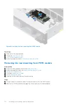
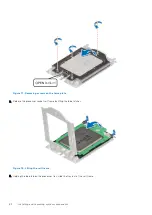

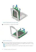
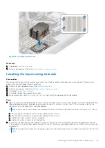
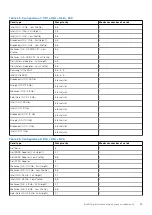
Figure 80. Placing the processor tray into the rail frame
2. Push the rail frame down until the blue latches lock into place.
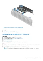
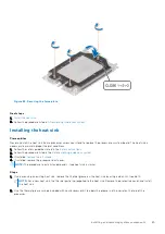
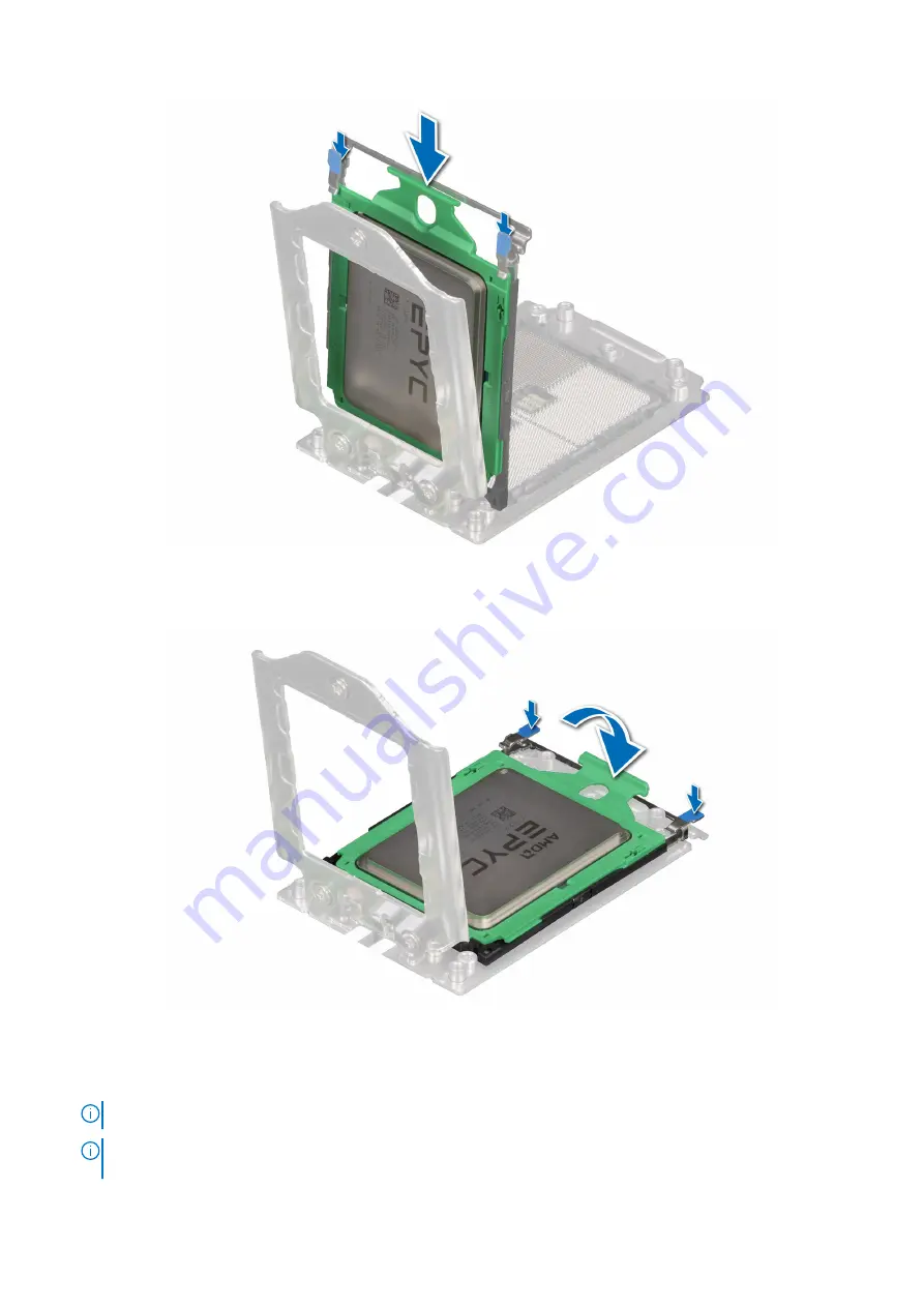
Figure 81. Closing the rail frame
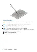
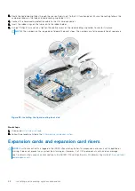
3. Secure the force plate to the processor socket base by tightening the screws in the sequence 1, 2, and 3. When all three
screws are fully threaded, the socket is then actuated. The three screws are tightened to a torque value of 12.0 ± 1.2 lbf-in.
NOTE:
The screw numbers are marked on the force plate.
NOTE:
Press the force plate while tightening the screws to avoid tilting of the processor cover out of the processor
socket.
84
Installing and removing system components
Содержание E68S
Страница 19: ...Figure 14 Service information System overview 19 ...
Страница 28: ...Cable routing Figure 18 12x 3 5 inch Figure 19 8 x 3 5 inch 28 Installing and removing system components ...
Страница 30: ...Figure 22 24 x 2 5 inch with NVMe Figure 23 16 x 2 5 inch 30 Installing and removing system components ...
Страница 31: ...Figure 24 8 x 2 5 inch with NVMe Figure 25 8 x 2 5 inch with NVMe Installing and removing system components 31 ...


