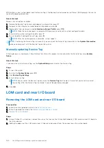
BIOS detects a new system board, and the Service Tag in the backup Flash drive device is different, BIOS prompts the user to
restore the backup information.
About this task
Below is a list of options available:
1. Restore the Service Tag, license, and diagnostics information, press
Y.
2. Navigate to the Lifecycle Controller based restore options, press
N.
3. Restore data from a previously created
Hardware Server Profile
, press
F10.
NOTE:
When the restore process is complete, BIOS prompts to restore the system configuration data.
4. To restore the system configuration data, press
Y
5. To use the default configuration settings, press
N
NOTE:
After the restore process is complete, system reboots.
NOTE:
If restoring the Service Tag is successful, you can check the Service Tag information in the
System Information
screen and compare it with the Service Tag on the system.
Manually updating Service Tag
After replacing a system board, if Easy Restore fails, follow this process to manually enter the Service Tag, using
System
Setup
.
About this task
If you know the system Service Tag, use the
System Setup
menu to enter the Service Tag.
Steps
1. Turn on the system.
2. To enter the
System Setup
, press
F2
.
3. Click
Service Tag Settings
.
4. Enter the Service Tag.
NOTE:
You can enter the Service Tag only when the
Service Tag
field is empty. Ensure that you enter the correct
Service Tag. After the Service Tag is entered, it cannot be updated or changed.
5. Click
OK
.
LOM card and rear I/O board
Removing the LOM card and rear I/O board
Prerequisites
1. Follow the safety guidelines listed in the
.
2. Follow the procedure listed in the
Before working inside your system
3.
Steps
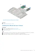
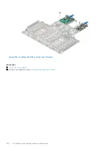
1. Using a Phillips # 2 screwdriver, remove the screws that secure the LAN on Motherboard (LOM) card and rear I/O board to
the system board.
2. Holding the edges, pull the LOM card or rear I/O board to disconnect from the connector on the system board.
166
Installing and removing system components
Содержание E68S
Страница 19: ...Figure 14 Service information System overview 19 ...
Страница 28: ...Cable routing Figure 18 12x 3 5 inch Figure 19 8 x 3 5 inch 28 Installing and removing system components ...
Страница 30: ...Figure 22 24 x 2 5 inch with NVMe Figure 23 16 x 2 5 inch 30 Installing and removing system components ...
Страница 31: ...Figure 24 8 x 2 5 inch with NVMe Figure 25 8 x 2 5 inch with NVMe Installing and removing system components 31 ...

