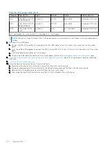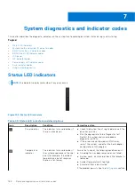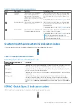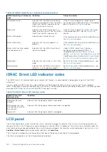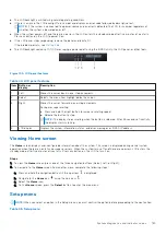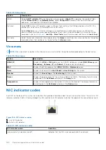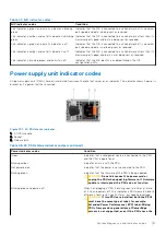
Table 48. AC PSU status indicator codes
Power indicator codes
Condition
same power rating. This results in a PSU mismatch
condition or failure to power on the system.
CAUTION:
If two PSUs are used, they must be of
the same type and have the same maximum output
power.
CAUTION:
When correcting a PSU mismatch, replace
the PSU with the blinking indicator. Swapping the
PSU to make a matched pair can result in an error
condition and an unexpected system shutdown. To
change from a high output configuration to a low
output configuration or vice versa, you must power
off the system.
CAUTION:
AC PSUs support both 240 V and 120
V input voltages. When two identical PSUs receive
different input voltages, they may output different
wattages, and trigger a mismatch.
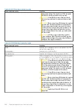
Table 49. DC PSU status indicator codes
Power indicator codes
Condition
Green
Indicates that a valid power source is connected to the PSU,
and the PSU is operational.
Blinking amber
Indicates an issue with the PSU.
Not powered on
Indicates that the power is not connected to the PSU.
Blinking green
When hot-plugging a PSU, it blinks green five times at a rate
of 4 Hz and powers off. This indicates a PSU mismatch due to
efficiency, feature set, health status, or supported voltage.
CAUTION:
If two PSUs are installed, both the PSUs
must have the same type of label; for example,
Extended Power Performance (EPP) label. Mixing
PSUs from previous generations of PowerEdge
servers is not supported, even if the PSUs have the
same power rating. This results in a PSU mismatch
condition, or failure to power on the system.
CAUTION:
If two PSUs are used, they must be of
the same type and have the same maximum output
power.
CAUTION:
When correcting a PSU mismatch, replace
the PSU with the blinking indicator. Swapping the
PSU to make a matched pair can result in an error
condition and an unexpected system shutdown. To
change from a High Output configuration to a Low
Output configuration or conversely, you must power
off the system.
CAUTION:
Combining AC and DC PSUs is not
supported.
188
System diagnostics and indicator codes
Содержание E68S
Страница 19: ...Figure 14 Service information System overview 19 ...
Страница 28: ...Cable routing Figure 18 12x 3 5 inch Figure 19 8 x 3 5 inch 28 Installing and removing system components ...
Страница 30: ...Figure 22 24 x 2 5 inch with NVMe Figure 23 16 x 2 5 inch 30 Installing and removing system components ...
Страница 31: ...Figure 24 8 x 2 5 inch with NVMe Figure 25 8 x 2 5 inch with NVMe Installing and removing system components 31 ...

