61
MCA
Pro
45/65/90/115
MCA-Pro ISM Rv.4.1 2/2017
Analogue heat output-based control (%)
The 0-10V signal controls the boiler output between
0% and 100%.
The minimum and maximum values are limited. The
minimum output is linked to the boiler's modulation
depth. The output varies between the minimum and
maximum value on the basis of the value determined
by the controller.
Jumper 2
Input signal
(V)
Heat output
(%)
Description
%
0 - 2.0
0 - 20
Boiler off
2.0 - 2.2
(1)
20 - 22
Hysteresis
2.0 - 10
(1)
20 - 100
Heat output
requested
(1) Dependent on the minimum modulation depth
(set speeds, standard 20%)
Analogue output (0-10 V)
The temperature or heat output can be chosen for this
feedback message. The two controls are described
briefly below.
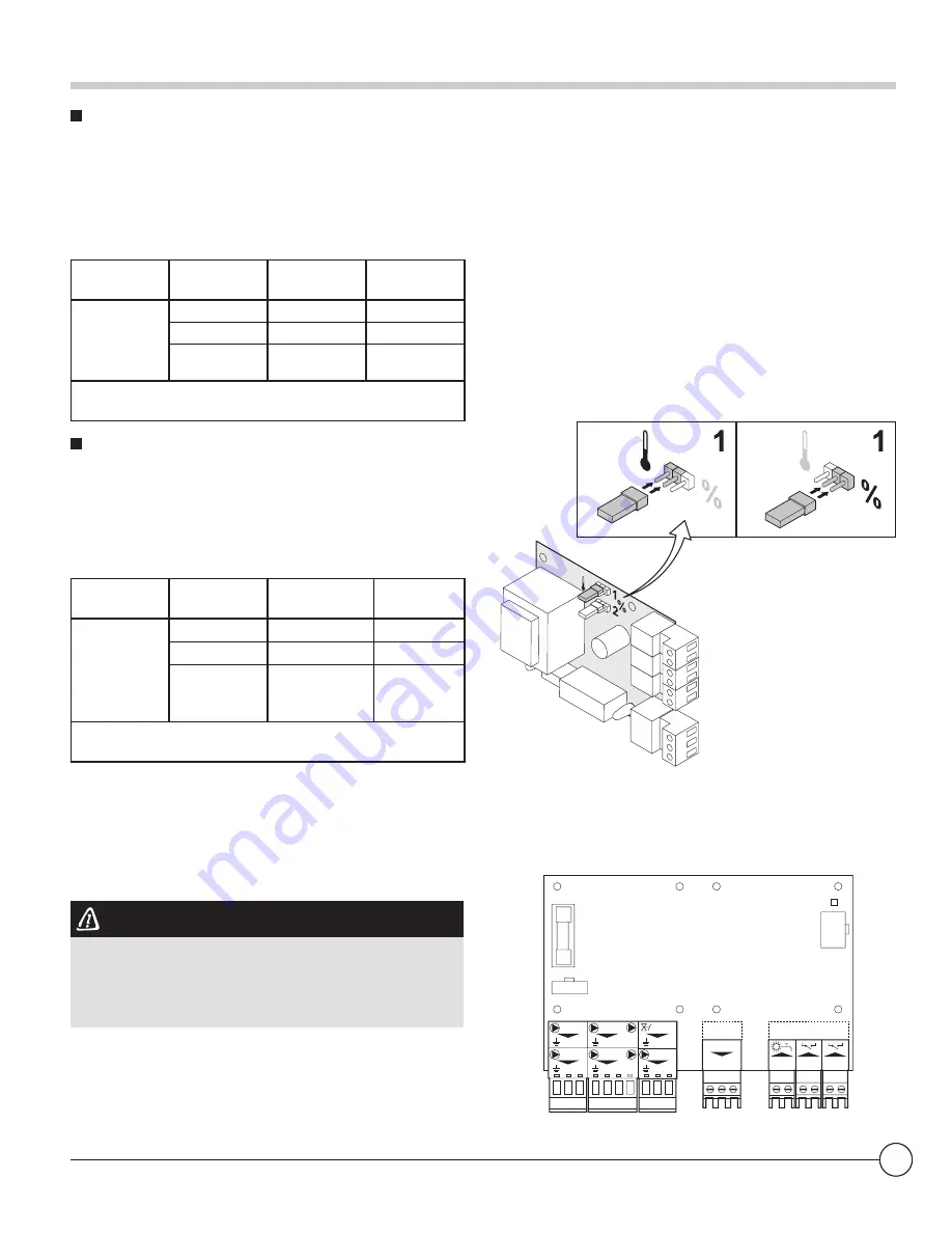
A jumper
(1)
on the interface is used to select either
temperature control (
) or heat output control (%).
Jumper1
Output
signal (V)
Temperature
ºF/ºC
Description
0
0-15
Boiler off
0.5
15-20
Alarm
2.0-10
(1)
20-100
Heat
output
supplied
(1) Dependent on the minimum modulation depth
(set speeds, standard 20%)
4.10.3. Connection possibilities for the PCB
(SCU-S02)
If the boiler is fitted with the control PCB (SCU-S02),
then this is automatically recognised by the automatic
control unit of the boiler.
CAUTION
On removing this PCB, the boiler will show fault code
E
:
38
. To prevent this fault, an auto-detect must be
carried out after removing this PCB.
See chapter: "Carrying out an auto-detect", page
81.
The LED status indicator D3 at the top right of the
control PCB indicates the status:
• Continuous signal: PCB working normally
• Flashing signal: No connection
• No signal: No voltage or faulty PCB (Check the
wiring)
4. Installation
Status
C
Nc No
C
Nc
No
Pump
NL
Pump
N
L
EgV
NL
EgV
NL
3wV
X3
SCU-SO2
X1
X4
X5
NC
3wV
NC D
D
X2
D3
Tsol Gps
Tsol
Gps
Hru
Hru
F 4AT
Содержание MCA Pro 115
Страница 45: ...45 MCA Pro 45 65 90 115 MCA Pro ISM Rv 4 1 2 2017 4 Installation H D G C B A E I J F ...
Страница 117: ......
Страница 118: ......
Страница 119: ......


