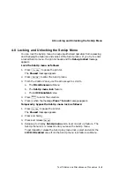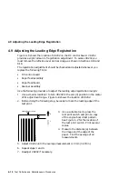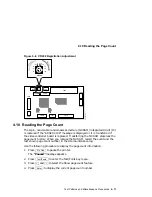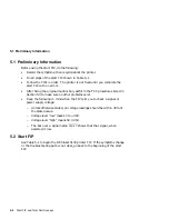
5.3 Total Call Concept (TCC) Procedure
5.3 Total Call Concept (TCC) Procedure
DSG-000622
Start
Chapter 5
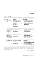
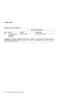
5.2 Start FIP
Chapter 6
6.1 Power Fault FIP
Error Message FIPs
Chapter 7
7.1 Jam FIPs
Chapter 8
8.1 Image Defects
Chapter 5
5.3 TCC Procedures
End
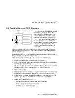
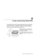
This section covers the total call concept
(TCC) for the DEClaser 5100. The
darkened section of the adjacent map
shows that the TCC procedure is the
final checkout section of the start FIP.
The TCC procedure involves inspecting
for damage and worn out parts and
involves cleaning the inside and outside
of the printer. Performing the TCC
procedure can reduce the number of
service calls.
To clean the paper path, use a clean lint-free cloth and the special vacuum
cleaner specified in Section D.3. Use a damp sponge to clean the covers and
external components.
While cleaning, look for broken plastic or metal components or for any signs of
damage. Replace any damaged components.
Before ending a service call, make sure you have done the following:
1.
Discuss the operation of the printer with the customer.
2.
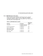
If more then 200,000 sheets have printed, perform the 200K maintenance
procedure (see Section 5.3.1).
The page count appears when you select the Show page count feature from
the Test/fonts key menu. See Figure A–1 for more information.
3.
Power on the printer.
4.
Either print several test prints or have the customer print a multipage job
to exercise the printer for a prolonged time period (5 minutes or more).
5.
If intermittent problems or mixed problems occur, note down the type of
problem. See Table 5–1 start FIP for a pointer to the specific FIP.
6.
Inspect all the paper path rollers for:
•
Surface contamination, uneven wear, dirt, or damage
•
Broken or disconnected pressure springs
•
Defective or unsecured bearings
Start FIP and Total Call Concept 5–5
Содержание DEClaser 5100
Страница 10: ......
Страница 13: ...DSG 000172 Notes 1 ...
Страница 14: ......
Страница 36: ...1 8 Resolution Graphics Enhancements Option Board DSG 000172 Notes 1 22 Physical and Functional Description ...
Страница 61: ...2 5 HVPSA Figure 2 12 EP ED Cartridge DSG 000612 2 1 3 4 5 6 7 Technical Description 2 25 ...
Страница 62: ...2 5 HVPSA DSG 000172 Notes 2 26 Technical Description ...
Страница 70: ...3 2 Control Panel Operation DSG 000172 Notes 3 8 Operating the Control Panel ...
Страница 90: ......
Страница 124: ...7 5 Phantom Jams DSG 000172 Notes 7 8 FIPs for Fixing Paper Jams ...
Страница 142: ...9 3 Assembly Gear 3 Remove the gear assembly through the rear of the printer DSG 000639 9 6 Removing and Replacing FRUs ...
Страница 152: ...9 7 Assembly Paper Delivery 3 Press and release the two clips DS G 0 006 46 1 9 16 Removing and Replacing FRUs ...
Страница 167: ...9 12 Board DC Control 1 2 4 5 7 8 9 6 3 10 DSG 000657 Removing and Replacing FRUs 9 31 ...
Страница 205: ...9 26 Guide HVPSA Contact Plate b Remove the HVPSA contact plate DS G 0 00 68 5 Removing and Replacing FRUs 9 69 ...
Страница 224: ...10 1 Field Replaceable Units DSG 000172 Notes 10 4 FRU Part Numbers ...
Страница 254: ...B 4 Connecting to OpenVMS VAX or ULTRIX Systems DSG 000172 Notes B 10 General Information ...
Страница 264: ...D 3 Tools DSG 000172 Notes D 4 Training Documentation and Tools ...
Страница 274: ......

