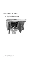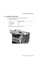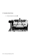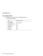
9.3 Assembly, Gear
9.3 Assembly, Gear
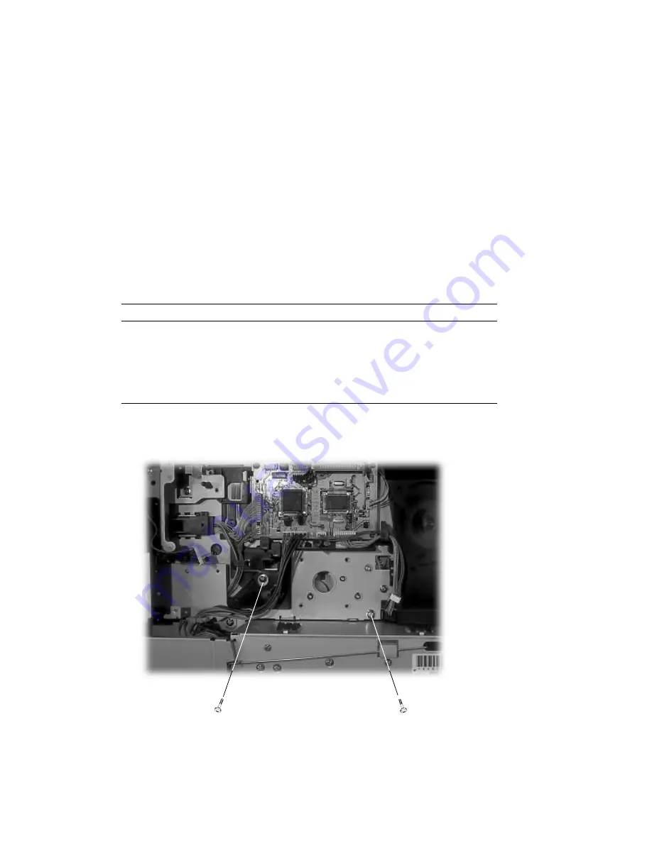
Use the following procedure to remove the gear assembly:
1.
Remove the following parts:
FRU
See section:
a.
Right-side cover
9.19
b.
Card cage
Section 9.16
c.
Video controller Board
Section 9.15
d.
Fusing unit
Section 9.25
e.
Main motor
Section 9.28
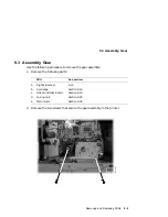
2.
Remove the two screws that secure the gear assembly to the printer.
DSG-000638
Removing and Replacing FRUs
9–5
Содержание DEClaser 5100
Страница 10: ......
Страница 13: ...DSG 000172 Notes 1 ...
Страница 14: ......
Страница 36: ...1 8 Resolution Graphics Enhancements Option Board DSG 000172 Notes 1 22 Physical and Functional Description ...
Страница 61: ...2 5 HVPSA Figure 2 12 EP ED Cartridge DSG 000612 2 1 3 4 5 6 7 Technical Description 2 25 ...
Страница 62: ...2 5 HVPSA DSG 000172 Notes 2 26 Technical Description ...
Страница 70: ...3 2 Control Panel Operation DSG 000172 Notes 3 8 Operating the Control Panel ...
Страница 90: ......
Страница 124: ...7 5 Phantom Jams DSG 000172 Notes 7 8 FIPs for Fixing Paper Jams ...
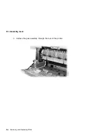
Страница 142: ...9 3 Assembly Gear 3 Remove the gear assembly through the rear of the printer DSG 000639 9 6 Removing and Replacing FRUs ...
Страница 152: ...9 7 Assembly Paper Delivery 3 Press and release the two clips DS G 0 006 46 1 9 16 Removing and Replacing FRUs ...
Страница 167: ...9 12 Board DC Control 1 2 4 5 7 8 9 6 3 10 DSG 000657 Removing and Replacing FRUs 9 31 ...
Страница 205: ...9 26 Guide HVPSA Contact Plate b Remove the HVPSA contact plate DS G 0 00 68 5 Removing and Replacing FRUs 9 69 ...
Страница 224: ...10 1 Field Replaceable Units DSG 000172 Notes 10 4 FRU Part Numbers ...
Страница 254: ...B 4 Connecting to OpenVMS VAX or ULTRIX Systems DSG 000172 Notes B 10 General Information ...
Страница 264: ...D 3 Tools DSG 000172 Notes D 4 Training Documentation and Tools ...
Страница 274: ......


