2.3 Xerographic Process
2.3.3 Development Process
@@@@
@@@@
@@@@
@@@@
@@@@
ÀÀÀÀ
ÀÀÀÀ
ÀÀÀÀ
ÀÀÀÀ
ÀÀÀÀ
@@@@
@@@@
@@@@
@@@@
@@@@
ÀÀÀÀ
ÀÀÀÀ
ÀÀÀÀ
ÀÀÀÀ
ÀÀÀÀ
@@@@
@@@@
@@@@
@@@@
@@@@
ÀÀÀÀ
ÀÀÀÀ
ÀÀÀÀ
ÀÀÀÀ
ÀÀÀÀ
@@@@
@@@@
@@@@
@@@@
@@@@
ÀÀÀÀ
ÀÀÀÀ
ÀÀÀÀ
ÀÀÀÀ
ÀÀÀÀ
@@@@
@@@@
@@@@
@@@@
@@@@
ÀÀÀÀ
ÀÀÀÀ
ÀÀÀÀ
ÀÀÀÀ
ÀÀÀÀ
@@@@
@@@@
@@@@
@@@@
@@@@
ÀÀÀÀ
ÀÀÀÀ
ÀÀÀÀ
ÀÀÀÀ
ÀÀÀÀ
@
@
@@
@
@
@@
@@
@@
@
@
À
À
ÀÀ
À
À
ÀÀ
ÀÀ
ÀÀ
À
À
@
@
@@
@
@
@@
@@
@@
@
@
À
À
ÀÀ
À
À
ÀÀ
ÀÀ
ÀÀ
À
À
@
@
@@
@
@
@@
@@
@@
@
@
À
À
ÀÀ
À
À
ÀÀ
ÀÀ
ÀÀ
À
À
@
@
@@
@
@
@@
@@
@@
@
@
À
À
ÀÀ
À
À
ÀÀ
ÀÀ
ÀÀ
À
À
@
@
@@
@
@
@@
@@
@@
@
@
À
À
ÀÀ
À
À
ÀÀ
ÀÀ
ÀÀ
À
À
@
@
@@
@
@
@@
@@
@@
@
@
À
À
ÀÀ
À
À
ÀÀ
ÀÀ
ÀÀ
À
À
Blade
AC Bias
(1600 Vp-p)
DC
Bias
-
-
-
-
-
-
-
-
-
-
+
+
+
+
+
+
+
+
+
+
+
+
+
Toner
Cylinder
Magnet
Developing
Cylinder
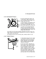
During the development process, the
invisible latent image is painted with
toner, producing a visible image on the
surface of the OPC drum.
The fixed magnet in the developer roller
attracts the magnetite-based toner to
the surface of the developer roller. The
doctor blade scrapes off the excess toner.
The dc bias on the development roller
charges the toner particles, while the
ac charge pushes and pulls the charged
particles toward the latent image on the
surface of the OPC drum.
On the OPC drum, the highly charged unexposed areas repel the toner. The
lesser charged, or exposed areas are painted with the toner, thus making the
image visible to the naked eye.
The developer dc bias varies from the primary dc bias (see Section 2.3.3).
2.3.4 Transfer Process
@@@
@@@
@@@
@@@
ÀÀÀ
ÀÀÀ
ÀÀÀ
ÀÀÀ
@@@
@@@
@@@
@@@
ÀÀÀ
ÀÀÀ
ÀÀÀ
ÀÀÀ
@@@
@@@
@@@
@@@
ÀÀÀ
ÀÀÀ
ÀÀÀ
ÀÀÀ
@@@
@@@
@@@
@@@
ÀÀÀ
ÀÀÀ
ÀÀÀ
ÀÀÀ
@@@
@@@
@@@
@@@
ÀÀÀ
ÀÀÀ
ÀÀÀ
ÀÀÀ
@@@
@@@
@@@
@@@
ÀÀÀ
ÀÀÀ
ÀÀÀ
ÀÀÀ
OPC
-
-
-
-
-
+
+
+
+
+
Toner
Transfer
Charging
Roller
Paper
+
+
+
+
+
+
+
+
-
-
-
-
-
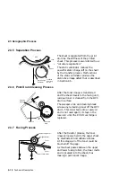
In the transfer process, the toner image
is attracted from the OPC drum to the
sheet of paper by the highly charged
transfer charging roller. The transfer
roller is made of a conductive foam
rubber-like compound.
During normal printer operation, the
porous surface of the transfer charging
roller attracts a small amount of toner,
which can degrade the quality of the
image. To purge this toner, a reverse
polarity is applied during initial rotation
(INTR) and between sheets. Frequent
jamming and other malfunctions can
overwhelm the transfer charging roller
purging process and cause image defects.
Technical Description 2–17
Содержание DEClaser 5100
Страница 10: ......
Страница 13: ...DSG 000172 Notes 1 ...
Страница 14: ......
Страница 36: ...1 8 Resolution Graphics Enhancements Option Board DSG 000172 Notes 1 22 Physical and Functional Description ...
Страница 61: ...2 5 HVPSA Figure 2 12 EP ED Cartridge DSG 000612 2 1 3 4 5 6 7 Technical Description 2 25 ...
Страница 62: ...2 5 HVPSA DSG 000172 Notes 2 26 Technical Description ...
Страница 70: ...3 2 Control Panel Operation DSG 000172 Notes 3 8 Operating the Control Panel ...
Страница 90: ......
Страница 124: ...7 5 Phantom Jams DSG 000172 Notes 7 8 FIPs for Fixing Paper Jams ...
Страница 142: ...9 3 Assembly Gear 3 Remove the gear assembly through the rear of the printer DSG 000639 9 6 Removing and Replacing FRUs ...
Страница 152: ...9 7 Assembly Paper Delivery 3 Press and release the two clips DS G 0 006 46 1 9 16 Removing and Replacing FRUs ...
Страница 167: ...9 12 Board DC Control 1 2 4 5 7 8 9 6 3 10 DSG 000657 Removing and Replacing FRUs 9 31 ...
Страница 205: ...9 26 Guide HVPSA Contact Plate b Remove the HVPSA contact plate DS G 0 00 68 5 Removing and Replacing FRUs 9 69 ...
Страница 224: ...10 1 Field Replaceable Units DSG 000172 Notes 10 4 FRU Part Numbers ...
Страница 254: ...B 4 Connecting to OpenVMS VAX or ULTRIX Systems DSG 000172 Notes B 10 General Information ...
Страница 264: ...D 3 Tools DSG 000172 Notes D 4 Training Documentation and Tools ...
Страница 274: ......


