2.1 Print Engine Control
2.1.1 Video Controller Board and SmartPage
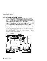
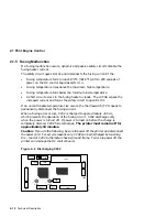
Figure 2–2 shows the video controller board mechanically and electronically
connecting and interfacing to the following standard and optional devices:
Standard devices:
•
The AppleTalk, parallel, and serial interface ports that allow direct
simultaneous connections to three different host computers
•
The operator panel provides users with control and status
•
The DC control board which operates the print engine
Optional devices:
•
One or two font cartridge
•
Optional hard disk drive
•
Optional XLI image enhancement board
•
Optional Ethernet network card
The video controller board accepts PostScript level 2 or PCL5E code files
from either the host or Ethernet interfaces and creates a bitmap image. The
bitmap is fed to the DC controller board as the
V DO
signal that is described in
Section 2.4.
Traditionally, an entire page is bitmapped into RAM before the printer is
commanded to feed and print. Such a system requires a considerable amount
of RAM memory.
SmartPage is the name of the process that the DEClaser 5100 printer uses to
create the printed image. Instead of bitmapping an entire page, this printer
bitmaps in bands. When one band is complete, it prints while the next band is
bitmapping. The SmartPage process uses about one-sixtieth as much RAM as
a full page bitmap requires.
2–4 Technical Description
Содержание DEClaser 5100
Страница 10: ......
Страница 13: ...DSG 000172 Notes 1 ...
Страница 14: ......
Страница 36: ...1 8 Resolution Graphics Enhancements Option Board DSG 000172 Notes 1 22 Physical and Functional Description ...
Страница 61: ...2 5 HVPSA Figure 2 12 EP ED Cartridge DSG 000612 2 1 3 4 5 6 7 Technical Description 2 25 ...
Страница 62: ...2 5 HVPSA DSG 000172 Notes 2 26 Technical Description ...
Страница 70: ...3 2 Control Panel Operation DSG 000172 Notes 3 8 Operating the Control Panel ...
Страница 90: ......
Страница 124: ...7 5 Phantom Jams DSG 000172 Notes 7 8 FIPs for Fixing Paper Jams ...
Страница 142: ...9 3 Assembly Gear 3 Remove the gear assembly through the rear of the printer DSG 000639 9 6 Removing and Replacing FRUs ...
Страница 152: ...9 7 Assembly Paper Delivery 3 Press and release the two clips DS G 0 006 46 1 9 16 Removing and Replacing FRUs ...
Страница 167: ...9 12 Board DC Control 1 2 4 5 7 8 9 6 3 10 DSG 000657 Removing and Replacing FRUs 9 31 ...
Страница 205: ...9 26 Guide HVPSA Contact Plate b Remove the HVPSA contact plate DS G 0 00 68 5 Removing and Replacing FRUs 9 69 ...
Страница 224: ...10 1 Field Replaceable Units DSG 000172 Notes 10 4 FRU Part Numbers ...
Страница 254: ...B 4 Connecting to OpenVMS VAX or ULTRIX Systems DSG 000172 Notes B 10 General Information ...
Страница 264: ...D 3 Tools DSG 000172 Notes D 4 Training Documentation and Tools ...
Страница 274: ......


