8.12 Registration
8.12 Registration
The image is out of place between the leading and trailing edges of
the sheet. Registration problems are caused by a malfunctioning
paper feed process or by a malfunction or maladjustment on the DC
control board.
The REGVR potentiometer, on the DC control board, provides
approximately 1 cm (0.93 in) of registration adjustment. There are
no side-to-side image positioning adjustments.
1.
Inspect the cassette or front tray for overloading or mechanical
damage.
2.
Make sure a correct type and size paper is being used. See
Digital Laser Printers Guide to Paper and Other Media for paper
specifications.
3.
Inspect the pickup and oblique rollers for damage, wear, or
surface contamination.
4.
Make sure the registration sensor lever works without sticking
or binding. If the sensor lever fails to work, replace the paper
feed unit.
5.
Adjusting the REGVR potentiometer to correct for a
malfunctioning component is not recommended. Find and
replace the malfunctioning part. See Section 4.9 for the
registration adjustment.
6.
Swap the following parts:
a.
Cassette or front pick up roller
b.
DC control board
c.
Paper feed assembly
FIPs For Fixing Image Defects 8–9
Содержание DEClaser 5100
Страница 10: ......
Страница 13: ...DSG 000172 Notes 1 ...
Страница 14: ......
Страница 36: ...1 8 Resolution Graphics Enhancements Option Board DSG 000172 Notes 1 22 Physical and Functional Description ...
Страница 61: ...2 5 HVPSA Figure 2 12 EP ED Cartridge DSG 000612 2 1 3 4 5 6 7 Technical Description 2 25 ...
Страница 62: ...2 5 HVPSA DSG 000172 Notes 2 26 Technical Description ...
Страница 70: ...3 2 Control Panel Operation DSG 000172 Notes 3 8 Operating the Control Panel ...
Страница 90: ......
Страница 124: ...7 5 Phantom Jams DSG 000172 Notes 7 8 FIPs for Fixing Paper Jams ...
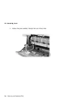
Страница 142: ...9 3 Assembly Gear 3 Remove the gear assembly through the rear of the printer DSG 000639 9 6 Removing and Replacing FRUs ...
Страница 152: ...9 7 Assembly Paper Delivery 3 Press and release the two clips DS G 0 006 46 1 9 16 Removing and Replacing FRUs ...
Страница 167: ...9 12 Board DC Control 1 2 4 5 7 8 9 6 3 10 DSG 000657 Removing and Replacing FRUs 9 31 ...
Страница 205: ...9 26 Guide HVPSA Contact Plate b Remove the HVPSA contact plate DS G 0 00 68 5 Removing and Replacing FRUs 9 69 ...
Страница 224: ...10 1 Field Replaceable Units DSG 000172 Notes 10 4 FRU Part Numbers ...
Страница 254: ...B 4 Connecting to OpenVMS VAX or ULTRIX Systems DSG 000172 Notes B 10 General Information ...
Страница 264: ...D 3 Tools DSG 000172 Notes D 4 Training Documentation and Tools ...
Страница 274: ......


