background image

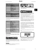
Data types supported by frequency transformer:

Data types

Description

3

Integer 16

4

Integer 32

5

Unsigned 8

6

Unsigned 16

7

Unsigned 32

9

Text  string

Unsigned means that there is no operational sign in the telegram.

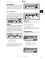
Example - Write a parameter value:
Parameter 202 

Output frequency high limit, f

MAX


 to be changed to 100

Hz. The value must be recalled after a mains failure, so it is written in
EEPROM.

PKE = E0CA Hex - Write for parameter 202 

Output frequency

high limit, f

MAX

IND = 0000 Hex

PWE

HIGH

 = 0000 Hex

PWE

LOW

 = 03E8 Hex - Data value 1000, corresponding to 100

Hz, see conversion.

The response from the slave to the master will be:

Example - Selection of a data value:
You wish to select kg/hour [20] in parameter 416 

Process units

. The value

must be recalled after a mains failure, so it is written in EEPROM.

PKE = E19F Hex - Write for parameter 416 

 Process units

IND = 0000 Hex

PWE

HIGH

 = 0000 Hex

PWE

LOW

 = 0014 Hex - Select data option kg/hour [20]

The response from the slave to the master will be:

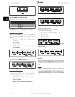
Example - Reading a parameter value:

The value in parameter 207 

Ramp up time 1

 is required.

The master sends the following request:

PKE = 10CF Hex - read parameter 207 

Ramp up time 1

IND = 0000 Hex

PWE

HIGH

 = 0000 Hex

PWE

LOW

 = 0000 Hex

If the value

in parameter 207 

Ramp-up time 1

 is 10 sec., the response from the slave

to the master will be:

Conversion:
Under the section entitled 

Factory Settings

 the various attributes of each

parameter are displayed. As a parameter value can only be transferred
as a whole number, a conversion factor must be used to transfer deci-
mals.

Example:
Parameter 201 

Output frequency, low limit f

MIN


 has a conversion factor

of 0.1. If you wish to preset the minimum frequency to 10 Hz, the value
100 must be transferred, as a conversion factor of 0.1 means that the
value transferred is multiplied by 0.1. The value 100 will thus be perceived
as 10.0.

3 Programming

VLT® Decentral FCD

72

MG.04.B8.02 - VLT is a registered Danfoss trademark

3  

Содержание VLT Decentral FCD 300

Страница 1: ...MG04B802 FCD 300 Operating Instructions Operating Instructions FCD 300 MAKINGMODERNLIVINGPOSSIBLE...

Страница 2: ...c entsprechend gekennzeichnet sein wenn das Ger t keinen internen berlastschutz f r die Motorlast besitzt und mit externem oder ferngesteuertem berlastschutz zu betreiben ist Danfoss VLT Frequenzumri...

Страница 3: ...r comprend un relais de surcharge s par UL508C par 56 6 1 1 3 Conformidad con UL508C De acuerdo con la norma UL508C los convertidores de frecuencia suministrados a partir del 9 de mayo de 2013 incluir...

Страница 4: ...on of Motor Rotation 19 Mains and Motor Connection with Service Switch 19 Connection of HAN 10E Motor Plug for T73 20 Parallel Connection of Motors 20 Motor Cables 21 Motor Thermal Protection 21 Brake...

Страница 5: ...to Profidrive Protocol 77 Parameter Group 5 Serial communication 79 Parameter Group 6 Technical Functions 84 4 All about FCD 300 87 Service 87 Warnings Alarm Messages 89 Warning Words Extended Status...

Страница 6: ...stration 2 3 Proper installation earthing 14 Illustration 2 4 T12 T16 T52 T56 16 Illustration 2 5 Versions with service switch 16 Illustration 2 6 T73 version with 17 Illustration 4 1 LCP2 plug 87 Ill...

Страница 7: ...Contents Table Table 4 1 LED diagnostics on decentralised FCD 300 88 Contents VLT Decentral FCD 4 MG 04 B8 02 VLT is a registered Danfoss trademark...

Страница 8: ...Series frequency converters with software version 1 5 x The software version number can be seen from parameter 640 Software version no NB Indicates something to be noted by the reader Indicates a gen...

Страница 9: ...otected against overloading pursuant to prevailing national and local regulations 4 The earth leakage currents are higher than 3 5 mA 5 Protection against motor overload is not included in the factory...

Страница 10: ...The FCD 300 is a part of the VLT frequency converter family which means similar funcionality programming and operating as the other family members 1 3 2 Flexible Installation Options 1 Stand alone clo...

Страница 11: ...tage V 4 Intermediate circuit coils Evens out the intermediate circuit current and limits the load on mains and components mains transformer cables fuses and contactors 5 Intermediate circuit capacito...

Страница 12: ...chanical dimensions in mm FCD 303 315 FCD 322 335 A 192 258 A1 133 170 B 244 300 B1 300 367 B2 284 346 C 142 151 C1 145 154 Cable Gland sizes M16 M20 M25 x 1 5 mm Space for cable inlets and service sw...

Страница 13: ...Stand alone mounted close to the motor Motor mounted or might be delivered pre mounted on a Danfoss Bauer geared motor Please contact the Danfoss Bauer sales organisation for further information The...

Страница 14: ...ral plate incl gas ket and screws for attaching to the installation box is available The appropriate drillings and gasket for the motor housing are applied locally Please make sure that the mechanical...

Страница 15: ...ng placed in cable trays sensitive cables may not be placed in the same cable tray as the motor cable If signal cables run across power cables this is done at an angle of 90 degrees Remember that all...

Страница 16: ...be suitable for high leakage current Use of original Danfoss installation box or installation kit 175N2207 is recommended 2 3 7 Caution PE connection The metal pin in the corner s of the electronic pa...

Страница 17: ...attached to screen clamps provided for that purpose Equalisation of voltage potential low frequencies To reduce alignment currents in the screen of the communication cable always apply a short earthi...

Страница 18: ...ternal ther mistor relay with EC Type Examination Certificate or compatible with the FCD 300 thermistor input If the FCD 300 thermistor protection is used the thermistor must be wired to terminals 31a...

Страница 19: ...rth voltage 300 V also during earth failure J1 and J2 can be removed to reduce leakage current Caution No correct RFI filtering 2 5 Electrical Installation 2 5 1 Location of Terminals Illustration 2 4...

Страница 20: ...with service switch Illustration 2 6 T73 version with motor plug and sensor plugs Version is supplied from Danfoss with wiring as shown VLT Decentral FCD 2 Installation MG 04 B8 02 VLT is a registere...

Страница 21: ...U1 W2 V1 U2 W1 V2 6 wires out of motor Delta connected U1 V1 W1 6 wires out of motor Star connected U2 V2 W2 to be interconnected separately optional terminal block PE Earth connection See Technical D...

Страница 22: ...as follows Terminal 96 connected to U phase Terminal 97 connected to V phase Terminal 98 connected to W phase The direction of rotation can be changed by switching two phases on the motor terminals 2...

Страница 23: ...values is maintained across the range The total current consumption of the motors is not to exceed the maximum rated output current IINV for the frequency converter Problems may arise at the start and...

Страница 24: ...nt see motor nameplate 2 5 11 Brake Resistor No 81 optional function 82 optional function Brake resistor terminals R R The connection cable to the brake resistor must be screened armoured Connect the...

Страница 25: ...unit in question In connection with very long control cables and analogue signals in rare cases depending on the installation 50 60 Hz earth loops may occur because of noise transmitted from mains sup...

Страница 26: ...rmistor 35 Common for external 24 V control back up supply Optional 36 External 24 V control back up supply Optional 42 Analog output for displaying frequency reference current or torque 46 Digital ou...

Страница 27: ...ng without connection to mains Please note that a warning of low voltage will be given when 24 V DC has been connected however there will be no tripping NB Use 24 V DC supply of type PELV to ensure co...

Страница 28: ...xamples NB Avoid leading the cables over the plugs to the electronics Don t loosen screw fixing the spring for the PE connection VLT Decentral FCD 2 Installation MG 04 B8 02 VLT is a registered Danfos...

Страница 29: ...asting stop inverted 2 2 6 2 Pulse Start Stop Pulse start using terminal 18 and pulse stop using terminal 19 In addition the jog frequency is activated via terminal 29 Par 302 Digital input Pulse star...

Страница 30: ...315 Terminal 60 min scaling 4 mA Par 316 Terminal 60 max scaling 20 mA 2 6 6 4 20 mA Reference 4 20 mA reference on terminal 60 and speed feedback signal on terminal 53 Par 100 Configuration Speed cl...

Страница 31: ...132 Hz 1 Par 203 Reference range Min ref Max ref 0 Par 204 Min reference 50 Hz Par 205 Max reference 50 Hz Par 302 Digital input Start 7 Par 304 Digital input Coasting stop inverted 2 Par 308 Analogue...

Страница 32: ...ence 2 10 00 Par 217 Preset reference 3 25 00 Par 218 Preset reference 4 35 00 Setup 2 contains the following preset references Par 215 Preset reference 1 40 00 Par 216 Preset reference 2 50 00 Par 21...

Страница 33: ...ailed parameter settings under Control of mechanical brake NB Do not use the internal relay for DC brakes or brake voltages 250 V 2 6 10 Counter Stop via Terminal 33 The start signal terminal 18 must...

Страница 34: ...ess this function has been programmed as Locked 1 via parameter 018 Lock for data changes 3 1 2 Control Keys for Parameter Setup The control keys are divided into functions in such a way that the keys...

Страница 35: ...by disconnecting the voltage to the motor or the frequency converter JOG changes the output frequency to a preset frequency while the key is held down Can be set to active or inactive via parameter 01...

Страница 36: ...ncy x scaling Motor current A Torque Power kW Power HP Motor voltage V DC link voltage V Thermal load motor Thermal load Hours run hours Digital input binary Pulse input 29 Hz Pulse input 29 Hz Pulse...

Страница 37: ...e both in the Menu mode and in the Quick menu mode Structure for Quick menu mode v Menu mode In addition to having a name each parameter is linked up with a number which is the same regardless of the...

Страница 38: ...e procedure for changing data will be the same Pressing the CHANGE DATA key gives access to changing the selected parameter following which the underlining in line 4 will flash on the display The proc...

Страница 39: ...de stop com mands transmitted via the digital inputs or via serial communi cation 3 the STOP RESET and JOG keys on the condition that these are active If Local operation 1 is selected the adjustable f...

Страница 40: ...er values Setup 1 4 1 4 are four individual Setups which can be selected as required Multi Setup 5 is used where remote controlled shifts between the four Set ups via a digital input or via serial com...

Страница 41: ...cy x scaling frequency x scale 5 Motor current A Motor current A 6 Torque Torque 7 Power kW Power kW 8 Power HP Power HP US 9 Motor voltage V Motor voltage V 11 DC link voltage V DC link voltage V 12...

Страница 42: ...t has registered 010 Small display line 1 1 Value See par 009 Large display readout Analog input 53 V 17 Function In this parameter the first of three data values can be selected that is to be display...

Страница 43: ...n of choice If Disable 0 is selected in this parameter the FWD REV key will be disabled See also parameter 200 Output frequency range 017 Local reset of trip Value Not active DISABLE 0 Active ENABLE 1...

Страница 44: ...4 User defined Quick Menu is set to Active 1 Up to 20 parameters can be selected for the user defined Quick Menu NB Please note that this parameter can only be set using an LCP 2 control panel See Ord...

Страница 45: ...al must be added from the proc ess and the process regulator must be set in parameter group 400 Special functions Process closed loop is not active if a DeviceNet card is mounted and Instance 20 70 or...

Страница 46: ...tor tuning AMT Value Optimisation off AMT off 0 Optimisation on AMT start 2 Function Automatic motor tuning is an algorithm that measures stator resistance RS without the motor axle turning This means...

Страница 47: ...reso nance phenomena Description of choice If 0 is selected there will be no reduction If 100 is selected the volt age is reduced to 50 at no load 119 High start torque Value 0 0 0 5 sec 0 0 sec Funct...

Страница 48: ...eter 122 Function at stop is to be activated Description of choice Set the required output frequency NB If parameter 123 is set higher than parameter 130 then the start delay function parameter 120 an...

Страница 49: ...if you want a trip when the motor is overloaded according to the calculations Select ETR warning 1 4 if you want a warning when the motor is over loaded according to the calculations You can also prog...

Страница 50: ...rallel coupled motors and in the case of quick load changes Too high load compensation may lead to instability 135 U f ratio Value 0 00 20 00 V Hz Depends on unit Function This parameter enables a shi...

Страница 51: ...Gain AC brake Value 1 00 1 50 1 30 Function This parameter is used to set the AC brake Using par 144 it is possible to adjust the size of the generator torque that can be applied to the motor without...

Страница 52: ...Output frequency range the minimum frequency is of no significance Description of choice The value chosen can range from 0 0 Hz to the frequency set in param eter 202 Output frequency high limit fMAX...

Страница 53: ...lected in parameter 100 Configuration Description of choice Select the required range 204 Minimum reference Ref MIN Value Par 100 Config Open loop 0 100 000 000 par 205 RefMAX 0 000 Hz Par 100 Config...

Страница 54: ...om the rated motor fre quency fM N parameter 104 Motor frequency f M N to 0 Hz provided no overvoltage arises in the inverter because of generating operation of the motor Description of choice Set the...

Страница 55: ...ling 10 V When parameter 214 Reference function is set to Sum 0 one of the preset Preset references par 215 218 is added to the external referen ces as a percentage of the reference range If terminal...

Страница 56: ...Description of choice If Catch up is active via a digital input the percentage value in parameter 219 Catch up Slow down reference will be added to the remote control led reference If Slow down is ac...

Страница 57: ...limit FBLOW a warning is given Parameters 223 228 Warning functions are out of function during ramp up after a start command and after a stop command or during stop The warning functions are activated...

Страница 58: ...or terminal 29 and 33 Function In these parameters 302 307 Digital inputs it is possible to choose be tween the different enabled functions related to the digital inputs ter minals 18 33 Description o...

Страница 59: ...e is to be increased or reduced by a programmable percentage value set in parameter 219 Catch up Slow down reference Slow down Catch up Function 0 0 Unchanged speed 0 1 Increase by value 1 0 Reduce by...

Страница 60: ...on 0 Reference reference 1 Feedback feedback 2 Wobble WOBB DELTA FREQ 10 Function This parameter allows a choice between the different functions available for the input terminal 60 Scaling of the inpu...

Страница 61: ...erminal 55 If the output is used as a current output the resulting resistance from the equipment connected may not exceed 500 Description of choice No function Is selected if the analogue output is no...

Страница 62: ...High current IHIGH Feedback higher than FBLOW the feedback value is higher than the value set in parameter 227 Warning Low feedback FBLOW Feedback lower than FBHIGH the feedback value is lower than t...

Страница 63: ...response to a stop command All six data selections contain a precise stop routine thus ensuring a high level of repeat accuracy The selections are a combination of the functions described below NB Pu...

Страница 64: ...is selected the adjustable frequency drive will carry out a reset if there has been a fault in connection with the mains failure The motor may start without warning 406 Automatic restart time Value 0...

Страница 65: ...the display when the maximum feedback has been obtained on the selected feedback input parameter 308 314 Analogue inputs 416 Process units Value No unit No unit 0 1 ppm ppm 2 rpm rpm 3 bar bar 4 Cycl...

Страница 66: ...regulation closed loop is selected in parameter 100 Con figuration the unit is defined in parameter 416 Process units Feedback A feedback range must be preset for both regulators At the same time this...

Страница 67: ...equency of less than 1 6 Hz The appropriate time constant is selected in Speed Regulation in parameter 421 Speed PID lowpass filter time and in Process Regulation in parameter 444 Process PID lowpass...

Страница 68: ...ors change Description of choice Quick control is obtained by a long differential time However if this time is too long it can make the process unstable When the differential time is 0 ms the D functi...

Страница 69: ...k signal increases select Normal 0 If the adjustable fre quency drive is to increase the output frequency in case the feedback signal increases select Inverse 1 438 Proces PID anti windup Value Not ac...

Страница 70: ...d by a first order lowpass filter to reduce the noise s impact on the process regulation This can be an advantage e g if there is a lot of noise on the signal Description of choice Select the required...

Страница 71: ...on The user sets the voltage by which the level for resistor braking is re duced It is only active when resistor in parameter 400 is selected Description of choice The greater the reduction value the...

Страница 72: ...se time back to the master will be a maximum of 20 ms and there will be pause of at least 2 characters Pause time min 2 characters Response time min 2 characters Response time max 20 ms The time betwe...

Страница 73: ...1 0 1 0 0 D4H 3 7 4 Data Character Byte The structure of data blocks depends on the type of telegram There are three types of telegram and the type of telegram applies for both control telegrams mast...

Страница 74: ...ameter 615 Error code must be read PKE 1267 Hex read parameter 615 Error code IND 0001 Hex Index no 1 The frequency converter will respond in the parameter value block PWE with a fault code value from...

Страница 75: ...EHIGH 0000 Hex PWELOW 0014 Hex Select data option kg hour 20 The response from the slave to the master will be Example Reading a parameter value The value in parameter 207 Ramp up time 1 is required T...

Страница 76: ...215 218 Preset reference according to the following table Preset ref Parameter Bit 01 Bit 00 1 215 0 0 2 216 0 1 3 217 1 0 4 218 1 1 NB In parameter 508 Selection of preset reference a se lection is...

Страница 77: ...t 10 0 causes the control word to be ignored Bit 10 1 causes the control word to be used This function is relevant because the control word is always contained in the telegram regardless of which type...

Страница 78: ...Local remote operation is selected It is not possible to control the frequency converter via serial communi cation Bit 09 1 means that it is possible to control the frequency converter via serial comm...

Страница 79: ...er 323 Relay output the output relay will be activated when the output frequency is 0 Hz Bit 00 01 02 1 means that the frequency converter can start the motor if the other starting conditions are fulf...

Страница 80: ...OFF3 or Coasting stop Bit 02 1 means that Bits 00 01 02 and 03 in the control word are 1 and that the frequency converter has not tripped Bit 03 No trip trip See description under Status word accordi...

Страница 81: ...e value is first converted to 1 complement and then 1 is added binarily to obtain 2 complement 2000 Hex 0010 0000 0000 0000 0000 1 complement 1101 1111 1111 1111 1111 1 2 complement 1110 0000 0000 000...

Страница 82: ...choice between controlling the adjustable frequency drive via the digital inputs and or via the serial port If Serial port 1 is selected the relevant command can only be activated if a command is give...

Страница 83: ...nput Ser port Function 0 0 DC braking 0 1 Motor running 1 0 DC braking 1 1 Motor running Logic and 2 Dig input Ser port Function 0 0 DC braking 0 1 Motor running 1 0 Motor running 1 1 Motor running Lo...

Страница 84: ...ication 1 Setup msb Setup lsb Function 0 0 Setup 1 0 1 Setup 2 1 0 Setup 3 1 1 Setup 4 Logic and 2 Bus Setup msb Bus Setup lsb Dig Setup msb Dig Setup lsb Setup no 0 0 0 0 1 0 0 0 1 1 0 0 1 0 1 0 0 1...

Страница 85: ...and activate a cut out 515 544 Data readout Value Par no Description Display text Unit 515 Res reference REFERENCE 516 Res reference Unit REFERENCE UNIT Hz rpm 517 Feedback Unit FEEDBACK UNIT Par 416...

Страница 86: ...ed status word and alarm word Control word parameter 539 Gives the present control word on the frequency converter in Hex See Serial communication for the FCD 300 Warning word parameter 540 States whe...

Страница 87: ...temperature faults that have been registered on the frequency converter s heat sink Parameter 605 Number of overvoltages Gives the number of overvoltages of the intermediate circuit voltage in the fre...

Страница 88: ...start up the frequency converter If the frequency converter comes into Normal Display mode the test is OK Remove the test connector and the frequency converter is ready for operation Parameter 620 Op...

Страница 89: ...software section number appears here Parameter 640 Nameplate Software version The unit s present software version number appears here Example 1 00 Parameter 641 Nameplate BMC software identification T...

Страница 90: ...t all parameters It displays parameters in six different languages The FCD 300 holds a log with valuable information on failure Information on the most recent 10 faults is stored and indexed in three...

Страница 91: ...rface working but no communication with master See field bus manual for specific info Not relevant for non field bus device Off Status for the field bus not OK not relevant for non field bus device 3...

Страница 92: ...AMT TYPE DATA FAULT X 54 AMT wrong motor AMT WRONG MOTOR X 55 AMT timeout AMT TIMEOUT X 56 AMT warning during AMT AMT WARN DURING AMT X 99 Locked LOCKED X LED indication Warning yellow Alarm red Trip...

Страница 93: ...table for the frequency converter ALARM 14 Earth fault There is a discharge from the output phases to earth either in the cable between the frequency converter and the motor or in the motor Turn off t...

Страница 94: ...18 4 1 3 Warning Words Extended Status Words and Alarm Words Warning words status words and alarm words appear in the display in Hex format If there are several warnings status words or alarms a total...

Страница 95: ...for use in moderate aggresive environments 4 2 2 Cleaning The enclosure IP66 NEMA type 4x indoor will offer protection against dirt and water ingress and is designed suitable for cleaning as performed...

Страница 96: ...ed the potentials of the group 18 19 20 27 29 33 are separated from all other input output In that case terminal 12 cannot be used for supply for the digital inputs on these terminals Serial communica...

Страница 97: ...foss NB FCD 300 with class 1A RFI filter is a product of the restricted sales distribution class according to IEC 61800 3 In a domestic environ ment this product may cause radio interference in which...

Страница 98: ...number 60 Current level 0 4 20 mA scaleable Input resistance Ri approx 300 Max current 30 mA Resolution for analogue inputs 10 bit Accuracy of analogue inputs Max error 1 of full scale Scan interval...

Страница 99: ...See section entitled Galvanic Isolation Control card 10 V DC output Terminal number 50 Output voltage 10 5 V 0 5 V Max load 15 mA The 10 V DC supply is galvanically isolated from the supply voltage P...

Страница 100: ...ror of 23 rpm Speed accuracy closed loop 30 3600 rpm Max error of 7 5 rpm All control characteristics are based on a 4 pole asynchronous motor Surroundings Enclosure IP 66 TYPE 4x indoor Enclosure T73...

Страница 101: ...in F10 Profibus DP V0 V1 3 Mbaud F12 Profibus DP V0 V1 12 Mbaud F30 DeviceNet F70 AS interface Installation box positions 22 24 T00 No Installation box T11 Installation box motor mount metric thread...

Страница 102: ...4 5 1 Ordering Form VLT Decentral FCD 4 All about FCD 300 MG 04 B8 02 VLT is a registered Danfoss trademark 99 4...

Страница 103: ...d local regulations 2 Typr gG gL pre fuses or corrosponding circuit brakers should be used If you want to maintain UL cUL branch circuit fuses according to NEC should be used Alternatively a circuit b...

Страница 104: ...es Yes 0 5 018 Data change lock Not locked Yes Yes 0 5 019 Operating status at power up Forced stop use saved ref Yes Yes 0 5 020 Lock for Hand mode Active Yes No 0 5 024 User defined Quick Menu Not a...

Страница 105: ...Yes 0 5 142 Leak reactance depends on motor selected No Yes 3 7 144 AC brake factor 1 30 No Yes 2 5 146 Reset voltage vector Off Yes Yes 0 5 147 Motor type General PNU Parameter description Factory se...

Страница 106: ...unction Manual reset Yes Yes 0 5 406 Aut restart time 5 sec Yes Yes 0 5 409 Trip delay overcurrent Off 61 sec Yes Yes 0 5 411 Switching frequency 4 5 kHz Yes Yes 0 6 413 Overmodulation function On Yes...

Страница 107: ...a readout Status word No No 0 6 537 Data readout Inverter temperature No No 0 5 538 Data readout Alarm word No No 0 7 539 Data readout Control word No No 0 6 540 Data readout Warning word No No 0 7 54...

Страница 108: ...er 27 Connection Of Mechanical Brake 29 Constant Torque 42 Control Cable 12 Control Cables 22 Control Of Mechanical Brake 21 Control Principle 8 Control Word 73 76 Counter Stop Via Terminal 33 30 Coun...

Страница 109: ...es 49 High Voltage Warning 6 12 I Initialise 85 Internal Fault 90 J Jog Frequency 52 Jog Ramp Time 51 L Language 36 Lcp 2 31 Lcp 2 Plug Optional 24 Lcp Copy 38 Leakage Reactance 48 Literature 100 Load...

Страница 110: ...Pid 66 Process Regulation 63 Process Units 62 Product Standard 94 Programming Setup 37 Protocol 83 Protocols 68 Pulse Max 29 59 Pulse Max 33 59 Pulse Start stop 26 Q Quick Menu Setup 41 Quick Menu Us...

Страница 111: ...stance 44 Status Led 41 Status Word 74 77 Sum 52 Surroundings 97 Switching Frequency 61 T Telegram Profile 82 Telegram Structure 69 Telegram Traffic 68 Terminal 42 58 Terminal 53 57 Terminal 60 57 Ter...

Страница 112: ......

Отзывы: