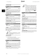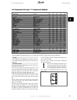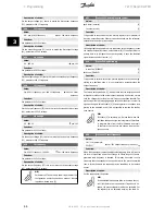
Pulse temperature (PULSE TEMP)
[30]
Control word bit 12 (CTRL. W. BIT 12)
[31]
Function:
The digital output can be used for giving the present status or warning.
The digital output (terminal 46) gives a 24 V DC signal when a given
condition is fulfilled.
Description of choice:
External Ref
MIN
- Ref
MAX
Par. 0-342.
An output signal is obtained, which is proportional to the resulting refer-
ence value in the interval Minimum reference, Ref
MIN
- Maximum refer-
ence, Ref
MAX
(parameters 204/205).
FB
MIN
-FB
MAX
Par. 0-342.
An output signal is obtained, which is proportional to the feedback value
in the interval Minimum feedback, FB
MIN
- Maximum feedback, FB
MAX
(pa-
rameter 414/415).
0-f
MAX
Par. 0-342.
An output signal is obtained, which is proportional to the output frequen-
cy in the interval 0 - f
MAX
(parameter 202
Output frequency, high limit,
f
MAX
).
0 - I
INV.
Par. 0-342.
An output signal is obtained, which is proportional to the output current
in the interval 0 - I
INV
.
0 - P
M,N
Par. 0-342.
An output signal is obtained, which is proportional to the present output
power. Par. 342 corresponds to the value set in parameter 102
Motor
power, P
M,N
.
0 - Temp.
MAX
Par. 0-342.
An output signal is obtained, which is proportional to the present heatsink
temperature. 0 Hz corresponds to a heatsink temperature of less than 20
°C, and 20 mA corresponds to 100 °C.
Control word bit 12,
bit 12 of the control word. The digital output will be
set/reset according to bit 12.
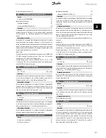
342
Terminal 46, max. pulse scaling
Value:
150 - 10000 Hz
5000 Hz
Function:
This parameter is used for setting the pulse output signal's maximum
frequency.
Description of choice:
Set the required frequency.
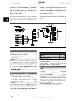
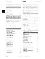
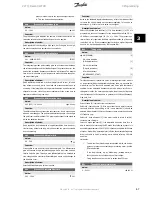
343
Precise stop function
Value:
Precise ramp stop (normal)
[0]
Counter stop with reset
(Count stop reset)
[1]
Counter stop without reset
(Count stop no reset)
[2]
Speed-compensated stop (Spd cmp stop)
[3]
Speed-compensated counter stop with reset
(Spd cmp cstop w. res)
[4]
Speed-compensated counter stop without reset
(Spd cmp cstop no res)
[5]
Function:
In this parameter you select which stop function is performed in response
to a stop command. All six data selections contain a precise stop routine,
thus ensuring a high level of repeat accuracy.
The selections are a combination of the functions described below.
NB!
Pulse start [8] may not be used together with the
precise stop function.
Description of choice:
Precise ramp stop
[0] is selected to achieve high repetitive precision at
the stopping point.
Counter stop
. Once it has received a pulse start signal the frequency
converter runs until the number of pulses programmed by the user have
been received at input terminal 33. In this way an internal stop signal will
activate the normal ramp down time (parameter 208).
The counter function is activated (starts timing) at the flank of the start
signal (when it changes from stop to start).
Speed compensated stop
. To stop at precisely the same point, regardless
of the present speed, a stop signal received is delayed internally when
the present speed is lower than the maximum speed (set in parameter
202).
Reset
.
Counter stop
and
Speed-compensated stop
can be combined with
or without reset.
Counter stop with reset
[1]. After each precise stop the number of pulses
counted during ramp down 0 Hz is reset.
Counter stop without reset
[2]. The number of pulses counted during
ramp down to 0 Hz is deducted from the counter value in parameter 344.
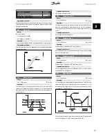
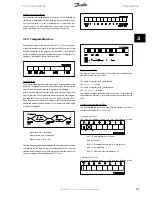
344
Counter value
Value:
0 - 999999
100000 pulses
Function:
In this parameter you can select the counter value to be used in the in-
tegrated precise stop function (parameter 343).
Description of choice:
The factory setting is 100000 pulses. The highest frequency (max. reso-
lution) that can be registered at terminal 33 is 67.6 kHz.
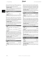
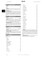
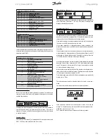
349
Speed comp delay
Value:
0 ms - 100 ms
10 ms
Function:
In this parameter the user can set the SYSTEM's delay time (Sensor, PLC,
etc.). If you are running speed-compensated stop, the delay time at dif-
ferent frequencies has a major influence on the way in which you stop.
Description of choice:
The factory setting is 10 ms. This means that it is assumed that the total
delay from the Sensor, PLC and other hardware corresponds to this set-
ting.
NB!
Only active for speed-compensated stop.
3 Programming
VLT® Decentral FCD
60
MG.04.B8.02 - VLT is a registered Danfoss trademark
3


