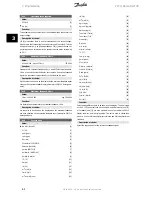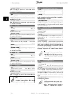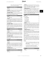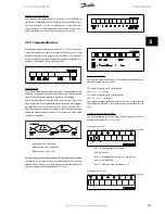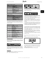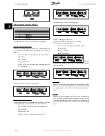
Description of choice:
Set the output voltage (U1) that is to match the first output frequency
(F1), parameter 424
F1 frequency
.
424
F1 frequency
Value:
0.0 - par. 426
F2 frequency
Par. 104
Motor frequency
Function:
See parameter 423
U1 voltage
.
Description of choice:
Set the output frequency (F1) that is to match the first output voltage
(U1), parameter 423
U1 voltage
.
425
U2 voltage
Value:
0.0 - 999.0 V
par. 103
Function:
See parameter 423
U1 voltage
.
Description of choice:
Set the output voltage (U2) that is to match the second output frequency
(F2), parameter 426
F2 frequency.
426
F2 frequency
Value:
Par. 424
F1 frequency
- par. 428
F3 frequency
Par. 104
Motor
frequency
Function:
See parameter 423
U1 voltage
.
Description of choice:
Set the output frequency (F2) that is to match the second output voltage
(U2), parameter 425
U2 voltage
.
427
U3 voltage
Value:
0.0 - 999.0 V
par. 103
Function:
See parameter 423
U1 voltage
.
Description of choice:
Set the output voltage (U3) that is to match the third output frequency
(F3), parameter 428
F3 frequency
.
428
F3 frequency
Value:
Par. 426
F2 frequency
- 1000 Hz
Par. 104
Motor frequency
Function:
See parameter 423
U1 voltage
.
Description of choice:
Set the output frequency (F3) that is to match the third output voltage
(U3), parameter 427
U3 voltage
.
NB!
Parameters 437-444 are only used if in parameter 100
Configuration
a selection has been made of
Process
regulation, closed loop.
[3].
437
Process PID normal/inverse control
Value:
Normal (normal)
[0]
Inverse (inverse)
[1]
Function:
It is possible to choose whether the process regulator is to increase/re-
duce the output frequency if there is a deviation between the reference/
setpoint and the actual process mode.
Description of choice:
If the adjustable frequency drive is to reduce the output frequency in case
the feedback signal increases, select
Normal
[0].If the adjustable fre-
quency drive is to increase the output frequency in case the feedback
signal increases, select
Inverse
[1].
438
Proces PID anti windup
Value:
Not active (DISABLE)
[0]
Active (ENABLE)
[1]
Function:
It is possible to select whether the process regulator is to continue reg-
ulating on a deviation even if it is not possible to increase/reduce the
output frequency.
Description of choice:
The factory setting is
Enable
[1], which means that the integration link is
initialised in relation to the actual output frequency if either the current
limit, the voltage limit or the max./min. frequency has been reached. The
process regulator will not engage again until either the error is zero or its
sign has changed. Select
Disable
[0] if the integrator is to continue inte-
grating on the deviation, even if it is not possible to remove the fault by
such control.
NB!
If
Disable
[0] is selected, it will mean that when the
deviation changes its sign, the integrator will first have
to integrate down from the level obtained as a result
of the former error, before any change in output fre-
quency occurs.
439
Process PID start frequency
Value:
f
MIN
- f
MAX
(parameter
201/202)
Par. 201
Output frequency, low limit, f
MIN
Function:
When the start signal comes, the adjustable frequency drive will react in
the form of
Open loop
and will not change to
Closed loop
until the pro-
grammed start frequency is reached. This makes it possible to set a
frequency that corresponds to the speed at which the process normally
runs, which will enable the required process conditions to be reached
sooner.
Description of choice:
Set the required start frequency.
NB!
If the adjustable frequency drive is running a the cur-
rent limit before the required start frequency is ob-
tained, the process regulator will not be activated. For
the regulator to be activated anyway, the start fre-
3 Programming
VLT® Decentral FCD
66
MG.04.B8.02 - VLT is a registered Danfoss trademark
3


