80
•
Technical Specifications
X64 Xcelera-HS PX8 User's Manual
J11: RS-422 Shaft Encoder Input
J11 provides an alternative method to connect shaft encoder signals to the Xcelera-HS PX8 board,
providing a higher maximum input signal frequency, but without the signal isolation provided by
the opto-coupled shaft encoder inputs (on J1 or J4). The user or imaging application enables, via
board parameters, which shaft encoder inputs are used for acquisition timing. For more information
see
Shaft Encoder Interface & Timing
" on page 44
.
J11 Pin Header Numbering Detail
2
4
6
8
10
1
3
5
7
9
J11 Signal Descriptions
Description
Pin #
Pin #
Description
Ground
1
2
Ground
Shaft Encoder Phase A +
3
4
Shaft Encoder Phase A -
Ground
5
6
Ground
Shaft Encoder Phase B +
7
8
Shaft Encoder Phase B -
Ground
9
10
Ground
Table 36: J11-Connector Details
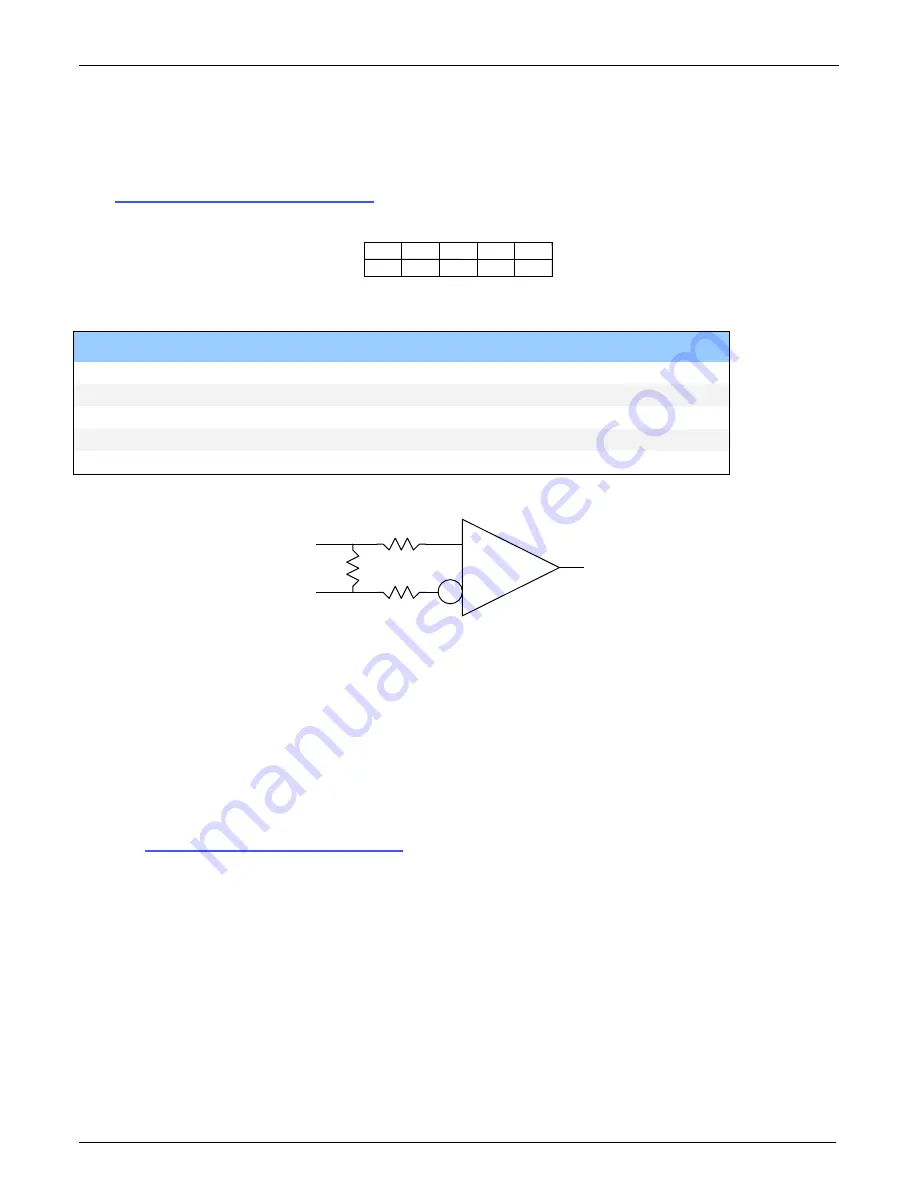
SE +
SE -
SE to FPGA
DS9637ACM
100
100
100
Figure 39: RS-422 Shaft Encoder Input Electrical Diagram
•
For single ended TTL signals, connect a bias voltage to the RS-422 (-) input to ensure correct
detection of the logic state of the TTL signal connected to the RS-422 (+) input. See the
following section for connection methods.
•
Maximum input voltage is 7V.
•
All inputs have a 100-ohm series resistor.
•
Maximum input signal frequency is 5 MHz.
•
Propagation Delay Time Low to High = 15ns Typical, 25ns Max.
•
Propagation Delay Time High to Low = 13ns Typical, 25ns Max.
•
See
Shaft Encoder Interface & Timing
" on page 44
for more information.
•
Refer to Sapera parameters:
CORACQ_PRM_SHAFT_ENCODER_ENABLE CORACQ_PRM_SHAFT_ENCODER_DROP
or refer to CORACQ_PRM_EXT_LINE_TRIGGER_ENABLE
CORACQ_PRM_EXT_LINE_TRIGGER_DETECTION
CORACQ_PRM_EXT_LINE_TRIGGER_LEVEL (fixed at RS-422)
CORACQ_PRM_EXT_LINE_TRIGGER_SOURCE
CORACQ_PRM_EXT_SHAFT_ENCODER_SOURCE
•
See also *.cvi file entries:
Shaft Encoder Enable, Shaft Encoder Pulse Drop, Shaft Encoder Source
or see External Line Trigger Enable, External Line Trigger Detection, External Line Trigger Level,
External Line Trigger Source.


