42
•
X64 Xcelera-HS PX8 Reference
X64 Xcelera-HS PX8 User's Manual
X64 Xcelera-HS PX8 Reference
Block Diagram
Host PCI Express X8 (or greater) Slot
DTE
Data-Transfer-Engine
with OLUT
PCI Express X8 Controller
Data
X64 Xcelera-HS PX8
Simplified Block Diagram
Data
Control
Data
ACU-Plus
Data
Lanes
HS-Link PHY
Control Lanes
Data Lanes
HS-Link
Interface
Control
Lanes
6
T
w
is
te
d
P
ai
rs
HS-Link PHY
CL
K
Control
TTL
* Dual Trigger In
Strob
e
Dual Shaft Encoder
Opto-coupled
Opto-coupled
I/O
Controller
12V
1.5A/
reset
Power Out
Power Gnd
5V
A
ux
. S
lo
t
Indicators
LE
D
s
PCIe /
Acquisition
Status
Status Indicator
1
Status Indicator
2
HS-Link Status
Operating Buffer
Memory
(256 MB)
&
Frame Buffer
Memory
(256 MB)
Destination
Buffer
Address Table
Opto-coupled
Quad General
Inputs
Opto-coupled
Quad General
Outputs
CC1 CC2CC3 CC4
TX
RX
1
Data
Contr
ol
6
T
w
is
te
d
P
ai
rs
1
Contr
ol
Data
Lanes
1
Control
Lanes
C
M
D
15
* Only one Trigger In on CMD15
LVA
L
FVA
L
1
6
6
1
1
CX4 #1
1
1
J1
1
Dual Shaft Encoder
**
RS-422
** User Selects which Shaft Encoder Input to use
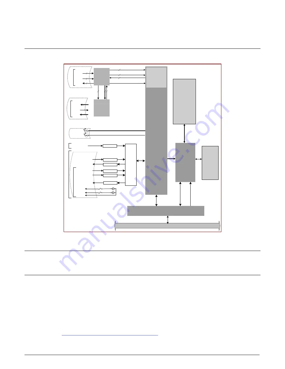
Figure 19: Block Diagram
Acquisition Timing
The HSLink acquisition timing specification will be published by the HSLink consortium.
Line Trigger Source Selection for Linescan
Applications
Line scan imaging applications require some form of external event trigger to synchronize line scan camera exposures to the
moving object. This synchronization signal is either an external trigger source (one exposure per trigger event) or a shaft
encoder source composed of a single or dual phase ((also known as a Q
uadrature) signal.
The X64 Xcelera-HS PX8 shaft encoder inputs provide additional functionality with pulse drop or
pulse multiply support along with error trapping event notifications such as “External Line Trigger
Too Fast” (see
Supported Events and Transfer Methods
” on page 49
).


