ESIE11-02
Functional Description
Part 2 – Functional Description
2–7
3
2
4
5
1
1.4
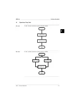
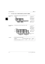
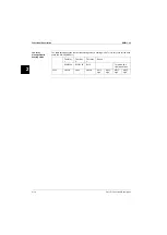
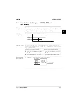
Operational Flow Chart
Flow chart
The flow chart below describes the operation of EUWA*5-24KBZW1.
Flow chart
The flow chart below describes the operation of EUWY*5-24KBZW1.
Power ON
Start cooling
Thermostat control
Stop
Power ON
Stop
Thermostat control
Start in cooling
Start in heating
Содержание EUWY 24KBZW1 Series
Страница 2: ......
Страница 8: ...ESIE11 02 vi Table of Contents 3 1 4 5...
Страница 10: ...Introduction ESIE11 02 viii 3 1 4 5...
Страница 12: ...ESIE11 02 1 2 Part 1 System Outline 3 1 1 5...
Страница 86: ...Wiring Layout ESIE11 02 1 76 Part 1 System Outline...
Страница 88: ...ESIE11 02 2 2 Part 2 Functional Description 3 1 2 5...
Страница 128: ...The Digital Controller ESIE11 02 2 42 Part 2 Functional Description 3 1 2 4 5...
Страница 130: ...ESIE11 02 3 2 Part 3 Troubleshooting 3 1 3 5...
Страница 168: ...ESIE11 02 4 2 Part 4 Commissioning and Test Run 3 1 4 5...
Страница 198: ...Test Run and Operation Data ESIE11 02 4 32 Part 4 Commissioning and Test Run 3 1 4 5...
Страница 200: ...ESIE11 02 5 2 Part 5 Maintenance 3 1 5...
Страница 210: ...ESIE11 02 4 Index 3 1 4 5...


