ESIE11-02
Functional Description
Part 2 – Functional Description
2–23
3
2
4
5
1
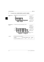
Illustration
compressor stop
function
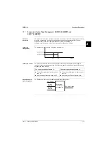
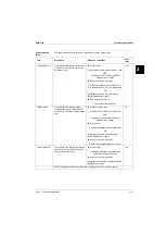
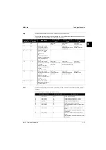
The illustrations below show the defrost cycle without and with compressor stop during the defrost
cycle.
Defrost cycles and
compressor stop
function
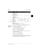
The table below describes the minimum and maximum defrost cycles without and with compressor
stop.
Defrost cycle
Start TimDefrMin
Start TimDefrMax
Start TimDefrMask
Time
Yes
No
ON
OFF
ON
OFF
Defrost
BusyC1
Compr.
DORev
Valve
Defrost cycle
Start TimDefrMin
Start TimDefrMax
Start TimDefrMask
Time
Yes
No
ON
OFF
ON
OFF
Defrost
BusyC1
Compr.
DORev
Valve
TimComprStop
Without compressor
stop
Minimum cycle
10 s
TimdefrMin
Maximum cycle
10 min
TimDefrMax
With compressor stop
Minimum cycle
130 s
TimCompr
TimdefrMin
Maximum cycle
12 min
TimCompr
TimDefrMax
Содержание EUWY 24KBZW1 Series
Страница 2: ......
Страница 8: ...ESIE11 02 vi Table of Contents 3 1 4 5...
Страница 10: ...Introduction ESIE11 02 viii 3 1 4 5...
Страница 12: ...ESIE11 02 1 2 Part 1 System Outline 3 1 1 5...
Страница 86: ...Wiring Layout ESIE11 02 1 76 Part 1 System Outline...
Страница 88: ...ESIE11 02 2 2 Part 2 Functional Description 3 1 2 5...
Страница 128: ...The Digital Controller ESIE11 02 2 42 Part 2 Functional Description 3 1 2 4 5...
Страница 130: ...ESIE11 02 3 2 Part 3 Troubleshooting 3 1 3 5...
Страница 168: ...ESIE11 02 4 2 Part 4 Commissioning and Test Run 3 1 4 5...
Страница 198: ...Test Run and Operation Data ESIE11 02 4 32 Part 4 Commissioning and Test Run 3 1 4 5...
Страница 200: ...ESIE11 02 5 2 Part 5 Maintenance 3 1 5...
Страница 210: ...ESIE11 02 4 Index 3 1 4 5...

