EE PRO for TI -89, 92 Plus
Equations - RL and RC Circuits
42
Entered Values
Calculated Results
Solution -
Upon examining the problem, all three equations are need to be solve the problem. Press
„
to display the input screen, enter all the known variables and press
„
to compute the solution.
-PQYP8CTKCDNGU.
AO*
4
A
Ω
+
AO#
V
AU
8U
A8
%QORWVGF4GUWNVUK.
A#
X.
A8
21.4 RC Step Response
These three equations describe the step response properties of an RC circuit.
The first equation defines the characteristic time constant,
ττ
, in terms of the
resistance R and the capacitance C. The last two equations compute the capacitor
voltage vC and current iC in terms of the step stimulus voltage Vs, the initial
capacitor voltage V0, time t, and time constant
ττ
.
τ = ⋅
R C
Eq. 21.4.1
vC
Vs
V
Vs e
t
= +
−
⋅
−
0
b
g
τ
Eq. 21.4.2
iC
Vs V
R
e
t
=
−
⋅
−
0
b
g
τ
Eq. 21.4.3
Example 21.4-
A 10_V step function is applied to an RC circuit with a 7.5_
Ω
resistor and a 67_nfarad
capacitor. The capacitor was charged to an initial potential of –10_V. What is the voltage across the.1_
µ
s after the
step function has been applied?
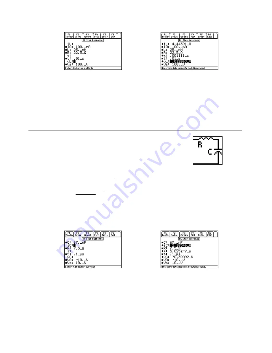
Entered Values
Calculated Results
Solution -
All three equations are needed to compute the solution for this problem. Press
„
to display
the input screen, enter all the known variables and press
„
to solve.
-PQYP8CTKCDNGU8
A8
%
APHCTCF
4
A
Ω
V
.1_
µ
s,
Vs
= 10_V
%QORWVGF4GUWNVUX%
A8
K%
A#


