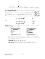
EE Pro for TI – 89, 92 Plus
Equations – Electrical Resonance
62
Chapter 25
Electrical Resonance
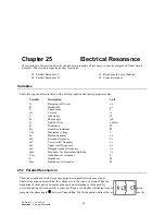
The equations in this section describe the electrical properties of resonance in circuits composed of ideal circuit
elements. The section is organized under four topics:
Parallel Resonance I
Parallel Resonance II
Resonance in Lossy Inductor
Series Resonance
Variables
The following variables are listed with a brief description and their appropriate units.
Variable
Description
Unit
α
Damping coefficient
r/s
β
Bandwidth
r/s
C
Capacitance
F
Im
Current
A
L
Inductance
H
θ
Phase angle
rad
Q
Quality factor
unitless
R
Resistance
Ω
Rg
Generator resistance
Ω
Vm Maximum
voltage
V
ω
Radian frequency
r/s
ω
0
Resonant frequency
r/s
ω
1
Lower cutoff frequency
r/s
ω
2
Upper cutoff frequency
r/s
ω
d
Damped resonant frequency
r/s
ω
m
Frequency for maximum amplitude
r/s
Yres
Admittance at resonance
S
Z
Impedance
Ω
Zres
Impedance at resonance
Ω
25.1 Parallel Resonance I
These ten equations describe resonance properties in parallel resonance circuits.
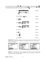
The first equation expresses Vm, the voltage across the circuit, in terms of Im, the
magnitude of the supplied current and the equivalent impedance of the parallel
circuit consisting of an inductor L, a capacitor C and a resistor R at the radian frequency
ω
. The second equation
computes the phase angle,
θ
, between Vm and Im. The third equation defines the resonant frequency
ω
0 from the


