EE Pro for TI – 89, 92 Plus
Equations – Polyphase circuits
61
-PQYP8CTKCDNGU
+.
A#
θ
ATCF
8R
A8
%QORWVGF4GUWNVU
+R
A#
2
A9
26
A9
8.
A8
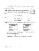
24.3 Power Measurements
These three equations for a two-watt meter connection are used to measure the total power of a
balanced network. The first two equations determine the watt meter readings W1 and W2 are
expressed from the line current IL, line voltage VL, and phase delay
θ
between the voltage and
the current. The final equation represents the total power, PT, delivered to the three-phase
load.
W
VL IL
1
6
=
⋅ ⋅
+
F
HG
I
KJ
cos
θ π
Eq.
24.3.1
W
VL IL
2
6
=
⋅ ⋅
−
F
HG
I
KJ
cos
θ π
Eq. 24.3.2
PT
VL IL
=
⋅ ⋅ ⋅
3
cos
θ
b g
Eq. 24.3.3
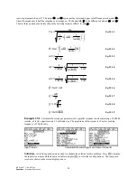
Example 24.3
- Given a line voltage of 110 V and a line current of 25 A and a phase angle of 0.1 rad, find the
wattmeter readings in a 2 wattmeter meter system.
Input variables
Computed results
Solution -
All of the equations are needed to compute the solution for this problem. Press
„
to display
the input screen, enter all the known variables and press
„
to solve the equation set. The computed
results are shown in the screen display above.
-PQYP8CTKCDNGU
+.
A#
θ
ATCF
8.
A8
%QORWVGF4GUWNVU
26
A9
9
A9
9
A9


