EE Pro for TI - 89, 92 Plus
Equations - OpAmp Circuits
74
Rf
Vo
IIf
=
max
Eq. 26.7.1
Rp
Rf
=
Eq. 26.7.2
CC
Vo
Rf Vrate
1
=
⋅
max
Eq. 26.7.3
RR
fd CC
1
1
2
1
=
⋅ ⋅ ⋅
π
Eq. 26.7.4
fd
Rf CC
=
⋅ ⋅
⋅
1
2
1
π
Eq. 26 7.5
Cp
f
Rp
=
⋅ ⋅
⋅
10
2
0
π
Eq. 26.7.6
Cf
f
Rf
=
⋅ ⋅
⋅
1
4
0
π
Eq. 26.7.7
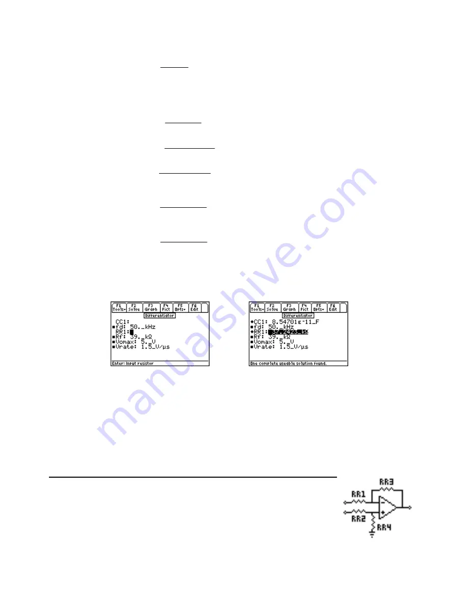
Example 26.7 -
A differentiator circuit designed with an OpAmp has a slew rate of 1.5 V/
µ
s. If the maximum
output voltage is 5 V, and the feedback resistor is 39 k
Ω
, what input capacitor and resistor are needed for the
amplifier with a characteristic frequency of 50 kHz?
Entered Values
Calculated Results
Solution -
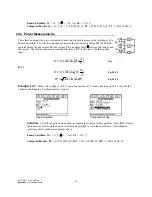
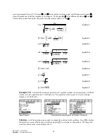
Use the third and fourth equations to compute the solution for this problem. Select these by
highlighting each equation and pressing the
¸
key. Press
„
to display the input screen, enter all the known
variables and press
„
to solve the equation. The computed results are shown in the screen displays above.
-PQYP8CTKCDNGUHF
AM*\
8TCVG
A8
µ
U
8QOCZ
A8
4H
AM
Ω
%QORWVGF4GUWNVU
%%
'A(
44
AM
Ω
26.8 Differential Amplifier
These four equations describe the primary relationships used in designing of a differential
amplifier. The first equation computes the differential gain Ad in terms of the input and
feeback resistors RR1 and RR3. The second equation shows the common-mode gain Aco
in terms of RR3, RR1, and the common-mode rejection ratio CMRR. The third equation
expands the definition of Ad from the first equation to accomodate a practical OpAmp
with a finite voltage gain Av. The final equation shows the common-mode gain due to
resistor mismatching Acc.


