EE Pro for TI-89, 92 Plus
Equations - Meters and Bridge Circuits
36
Lx CC RR RR
=
⋅
⋅
3
1
4
Eq.
20.5.1
Rx
CC RR
CC
RR
=
⋅
−
3
1
4
2
Eq.
20.5.2
Example 20.5-
A lossy inductor is plugged into an Owen bridge to measure its properties. The resistance branch
has 1000_
Ω
resistors and a capacitor of 2.25
µ
F on the non-resistor leg and 1.25_
µ
F capacitor on the resistor leg of
the bridge. A series resistance of 125_
Ω
connects the CC4 leg to balance the inductive element.
Entered Values
Calculated Results
Solution -
Press
„
to display the input screen, enter all the known variables and press
„
to solve the
equation. The computed results are shown in the screen display shown here.
-PQYP8CTKCDNGU
%%
A
µ
(
%%
A
µ
(
44
A
Ω
44
A
Ω
%QORWVGF4GUWNVU
.Z
AJGPT[
4Z
A
Ω
20.6 Symmetrical Resistive Attenuator
Tee Pad
Pi Pad
Bridged Pad
Balanced Pad
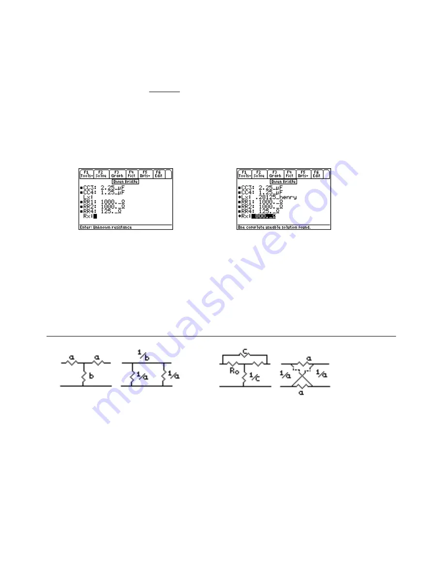
Balanced resistive networks are commonly used as attenuators in transmission line circuits. The three equations
below form the basis of the design for resistive attenuators in a Tee pad, a Pi pad, a bridged Tee pad or a balanced
pad configuration. These design equations compute the value of the multiplier in the circuit for a given an
attenuation loss dB, in decibels. The values of a, b or c define the attenuator network. The figure above show the
four key various configurations for the attenuator pads. For example, if the terminating resistance is 100 ohms, and
a 20 db attenuation is desired, computing a and b will be adequate to design a Tee pad or a Pi pad. The resistance of
each leg is computed by the terminating resistance by the multiplier factor.


