EE PRO for TI-89, 92 Plus
Equations - Solid State Devices
92
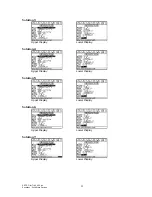
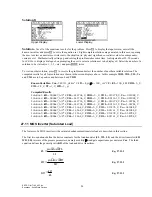
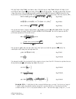
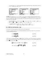
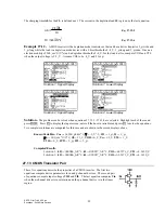
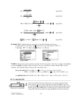
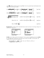
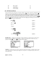
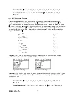
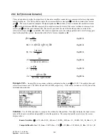
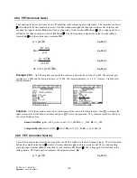
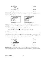
Solution -
Use the second through last equations to compute the solution for this problem. Select these by
highlighting each equation and pressing the
¸
key. Press
„
to display the input screen, enter all the known
variables and press
„
to solve the equation. The computed results are shown in the screen displays above.
-PQYP8CTKCDNGU
ε
QZ
ε
U
0C
'AEO@
φ
(
A8
φ
)%
8
3QZ
'A%EO@
VQZ
A
µ
85$
A8
%QORWVGF4GUWNVU
%QZ
A(O@
γ
A
√
8
3D
A%O@
3D
A%O@
86
A8
ZF
A
µ
27.9 MOS Transistor II
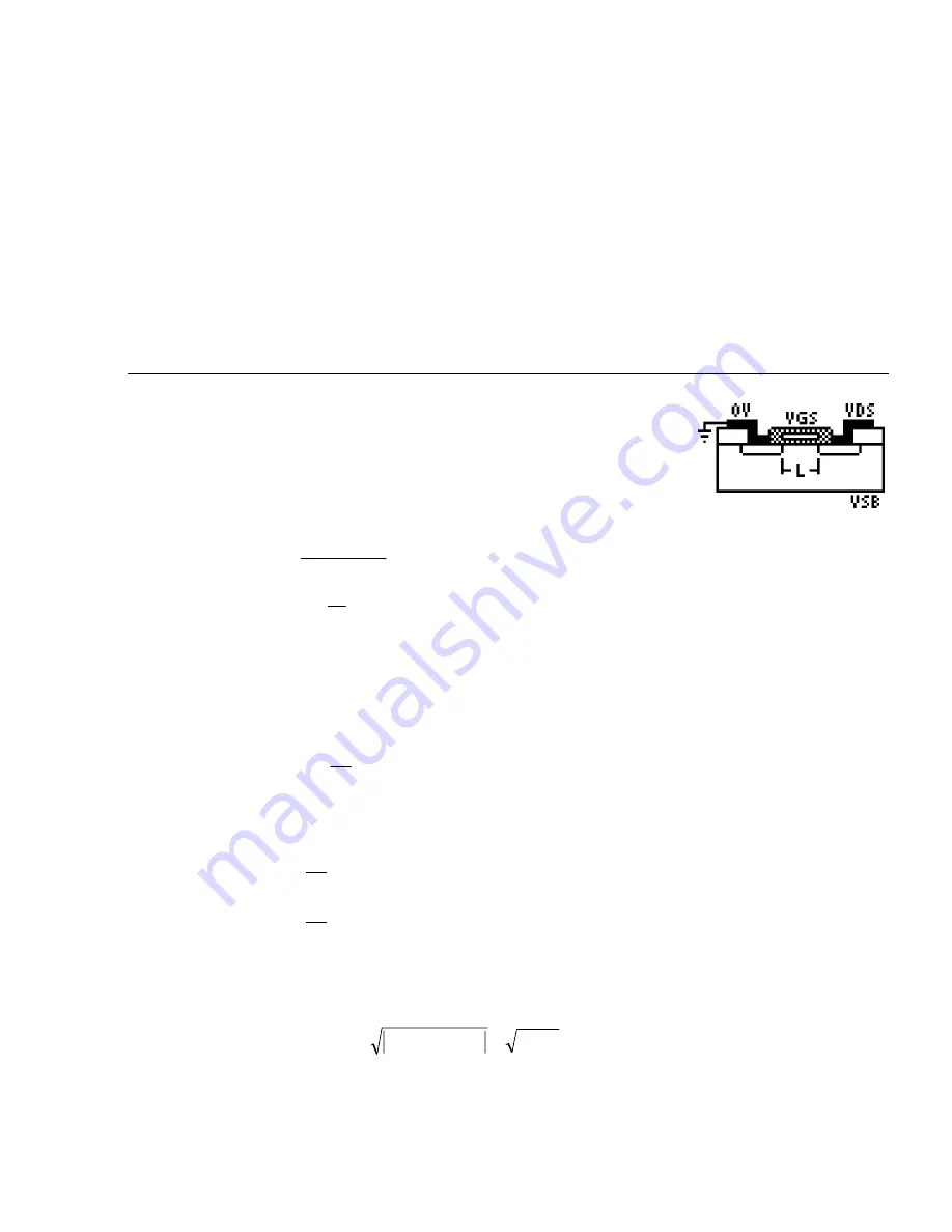
These equations describe the performance characteristics of a MOS transistor. The
first two equations give two alternate forms for the process constant kn1 in terms of
electron mobility
µ
n, oxide capacitance per unit area Cox, relative oxide permittivity
ε
ox, and oxide thickness tox. The third equation links the process constant kn1 to the
device constant kn, device length L, and width W.
kn
n Cox
1
=
⋅
µ
Eq. 27.9.1
kn
n ox
tox
1
0
=
⋅
⋅
µ ε
ε
Eq. 27.9.2
kn
kn
W
L
=
⋅
1
Eq. 27.9.3
The fourth equation defines IDmod the drain current, when the transistor is operating under saturation, in terms of kn,
gate voltage VGS, threshold voltage VT, modulation parameter
λ
, and drain voltage VDS. The basic physics behind
the increase in drain current comes from the channel widths being non-uniform under the gate because f a finite
potential difference between the source and the drain terminals.
ID
kn
VGS VT
VDS
mod
=
⋅
−
⋅ + ⋅
2
1
2
b
g b
g
λ
Eq. 27.9.4
The fifth equation computes the drain current ID under linear or saturated conditions in terms of kn, VGS, VT, and
VDS.
ID
kn
VGS VT VDS VDS
VGS VT
VDS
kn
VGS VT
else
=
⋅ ⋅
−
⋅
−
−
≤
⋅
−
R
S
||
T
|
|
U
V
||
W
|
|
2
2
2
2
2
b
g
c
h
b
g
,
,
Eq. 27.9.5
The expression for the threshold voltage VT is defined in terms of zero substrate bias threshold voltage VTO, body
coefficient
γγ
, substrate bias VSB, and Fermi potential
φφ
F.
VT
VT
F VSB
F
=
+ ⋅ − ⋅
+
−
⋅
0
2
2
γ
φ
φ
e
j
Eq. 27.9.6
The last four equations calculate performance parameters transconductance gm, transit time through the channel Ttr,
maximum frequency of operation ffmax, and drain conductance gd.


