Croplands HTP3 QMQ12 Скачать руководство пользователя страница 76

HT-OMSMART-A

76

Every 250 hours or Every Season  
- Whichever Comes Sooner

1.   Change oil and refill with 20W/30 oil. Attention 

should be made to remove trapped air behind the 
diaphragms by rocking from side to side as instructed.


 It is also good practise run the pump for 10 minutes 
without pressure, and then, top up with oil before 
working the pump.

2.   When changing the pump oil, check diaphragms and 

replace them if they are showing signs of wear.


 Diaphragm valves should be replaced every 400 
hours regardless of wear.


 This is normally a pre-season maintenance procedure 
which can be done easily as no special tools are 
required.


 You can avoid unnecessary down time in spraying 
seasons by carrying out preventative maintenance.

3.   Also check inlet and outlet valves and replace if worn. 

Worn valves not only reduce the output of the pump, 
but may reduce the life of the diaphragms.

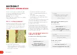
Excessive Diaphragm Failure

If you have excessive diaphragm failure check the 
following points. These will cause failure of diaphragms 
due to added stress or chemical attack.
1.   Most Important - Pump not being flushed out daily with 

clean water after use.

2.   Oil level too low allowing air between piston and 

diaphragm.

3.  Air leaks in suction line.
4.  Restricted suction line.

5.  Restriction through suction filter.
6.  Not cleaning suction filter regularly.
7.  Worn suction and discharge valves.
8.  Bypass line too small to carry full capacity of pump.
9.   In cold climates - frozen suction/discharge lines or 

water remaining in the pump after flushing.

10.  Incorrect air setting or no air in air chamber.
11.  Agitator excessively restricting bypass from pump.
12.   Diaphragm material construction incorrect for 

chemical or solution being pumped.

13.   Chemicals containing toluene or other aggressive 

solvents may require viton diaphragms - particularly  
if the pump is not properly flushed after use.

Pre-Season Servicing

For thorough pre-season servicing - check all aspects 
of the Quantum Mist and its operating components as 
outlined in the pre-delivery check list.

Pump Storage and Corrosion Protection

1.  Warm Climates


 If you operate in a warm climate with no chance of 
frost in the winter, you will not have any problems with 
frost damage.


 If you are storing your sprayer between seasons, ensure 
your pump has been thoroughly flushed with clean 
water. A good idea is to run a mixture of 1% solution 
of summer mineral spraying oil through the pump and 
plumbing system. Summer spraying oil is water-soluble 
oil such as DC-Tron. This will coat and protect all 
internal pump parts. Ensure this mixture is flushed out 
before spraying commences in the new season.

2.  Cold Climates


 For prolonged storage, an anti-freeze mixture can be 
flushed through the pump. Ensure this is thoroughly flushed 
out prior to the commencement of spraying again.


 If the pump is being stored overnight and a risk of 
freezing is imminent, drain all liquid from the pump 
and lines, including boom lines.
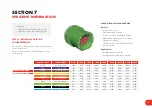
FILTERS

Filter Maintenance

Clean filters ensure that no solids enter the spraying system 
to block or damage pump or nozzles.
All filters should be cleaned regularly or after each 
spraying period.

Suction Filter

The suction filter should be cleaned regularly, or after each 
spray tank has been emptied.
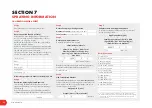
SECTION 9

LUBRICATION & MAINTENANCE

The pump suction valve CLOSED to the main tank

Содержание HTP3 QMQ12

Страница 1: ...MART A INCORPORATING QM 420 SPRAY FANS AND RECAPTURE SYSTEM QUANTUM MIST SMART SPRAYER OPERATORS MANUAL STOP BEFORE COMMENCING operation ENSURE you read understand this manual its contents and any add...

Страница 2: ...nd We welcome any feedback from you about our equipment On the back cover you will find our contact details and locations where our staff can be reached during business hours After hours you can email...

Страница 3: ...NS Safety first 45 Filters 45 Filling the sprayer 46 Setting sprayer pressure 46 Agitation 47 Mixing basket 47 Chemical probe 48 Calculate water chemical quantities 49 Proceed to spray 50 Flushing 51...

Страница 4: ...y to operate the machine CAUTION This Caution sign shows the potential for an incident An incident may include damage to the machine itself or possible injury to the operator WARNING This warning sign...

Страница 5: ...prayer s unique serial number the Sprayer s specification sheet a pre delivery checklist and outlines the Croplands Warranty policy Always contact your Croplands Dealer first and foremost for warranty...

Страница 6: ...Croplands Web site or for printed versions contact Croplands customer support and ask for part number GP SAFE A or later version if available OPERATORS SAFETY MANUAL www croplands com au STOP BEFORE...

Страница 7: ...maintenance schedules outlined in operator s manuals 5 Always read chemical manufacturers labels before use 6 Always observe all warnings on chemical products 7 Regularly check all nuts and bolts are...

Страница 8: ...op of inner arm Terracing versions are 3 80m high Maximum lengths from rear of the fan frames to the ball joint of the Micro Power Pack much the same position as a normal towbar are 2000 Lt 4450mm 515...

Страница 9: ...en pumps in lieu of PTO are also an option when a Micro Power Pack is fitted to the sprayer Agitation The agitation system is driven by the pump via twin supa flow venturi tank agitators bypass agitat...

Страница 10: ...es are fitted as standard Flotation tyres available as options Recapture System An optional 2 row drift reduction recapture system can be fitted to a 2 row QM Smart Spray This is ideally suited to coo...

Страница 11: ...M ARMS TIE RODS 14 HYDRAULIC SYSTEM 15 SPRAY PUMP 17 FUSION CONTROLLER SYSTEM CONNECTION 17 WINDCOMP HYDRAULICS 19 LIQUID SYSTEM OVERVIEW 20 TANKS SUCTION PLUMBING 20 PUMP PRESSURE PLUMBING 22 TIERED...

Страница 12: ...downwards to enable drainage The case drain is there for the unlikely event of blowing oil seals in the hydraulic motor Sprayers fitted with the WindComp feature will use 2 speed sensors left and righ...

Страница 13: ...pray rings to be manually shut off as required Screw the red cap in for stop out for normal diaphragm non drip Each spray ring has a draining flush tap on the exit FAN FRAMES BOOM ARMS TIE RODS Fan Fr...

Страница 14: ...s of adjustment holes in both the inner slide of the main boom and also the pull rod More details in Section 5 Each fan frame is connected to the boom arm or Hanger via a Swivel Head which incorporate...

Страница 15: ...pressures and temperatures Troubleshooting is also easier Note in some markets smaller tractors not requiring a Micro Power Pack the plumbing is more traditional using circuits of 4 or 6 fans For more...

Страница 16: ...fitted with a fan forced oil cooler The fan is thermostat controlled switching in at around 50 degrees C The Fusion system requires a separate wiring loom direct from power source tractor battery to p...

Страница 17: ...new Smart Sprayer features From battery to cab is a power loom MT90LOOM PWR and thereafter is the Fusion loom CHLOOM FUSION which connects to the ECU module mounted at the front of the sprayer The fro...

Страница 18: ...shows the main Fusion hydraulic block top boom control manifold middle and 8 spray section control valves below all installed in an optional control box with the lid removed Note the orientation of bl...

Страница 19: ...2 500 Note in the photo the coil circled closest to the main inlet outlet at position K controls the fans that spray to the right side and the coil below controls the left facing fans Note in some app...

Страница 20: ...F Flow meter G Suction filter from tank and into suction manifold of the pump H Chemical suction probe fitting I Quick fill connection J To Recapture system venturi TANKS SUCTION PLUMBING Smart Spraye...

Страница 21: ...he main tank and has a separate lid see green arrow The handwash tank is at the rear of the tank green circle The 4000 Flushing tank can also be remote filled via camlock coupling mounted near the mai...

Страница 22: ...present and take the appropriate safety measures Always wear gloves Sight Gauges All main tanks are fitted with both a front RH side and side LH Side sight gauges Inside of each clear sight hose is a...

Страница 23: ...tem if fitted Photo 2 shows 2 x suction filters for left inner left outer Recapture screens 6 Not fully shown in this photo are the motorised section valves 7 The pressure gauge is mounted either at t...

Страница 24: ...rings The choices are never ending Photo 1 shows inlet top and outlet tap at the bottom of the outer larger diameter spray ring To the inside shows the inner spray ring which has similar connections...

Страница 25: ...stands 1 x for the main sprayer chassis 2 x for the 3 point linkage frame This ensures safe stable storage when not connected to the tractor Always park the sprayer in a horizontal position and on fi...

Страница 26: ...ight hand side rear wheel The sensor needs to be 5mm from the target which in this case is the head of the wheel studs on the back of the axle The sensor is reading cm per pulse A GPS speed sensor Atl...

Страница 27: ...7 SAFETY FIRST 28 HOOK UP 28 FIT SETUP FUSION CONTROLLER TO THE TRACTOR 31 SETUP SPRAY PRESSURE 36 SET UP THE BOOMS 37 CONFIRMING FAN FUNCTIONALITY 42 PRE OPERATION CHECKLIST 43 SECTION 5 PRE OPERATIO...

Страница 28: ...shipping from the factory dealer 1 Adjust and fit the 2 or 3 point linkage self steer drawbar to the tractor 2 Connect the PTO shaft to the tractor and sprayer 3 Fit the hydraulic hoses to the tractor...

Страница 29: ...ew uncut PTO is supplied with the sprayer Follow the instructions below to fit the PTO shaft onto the Quantum Mist after transit Note for new installations the dealer will oversee the fitting of the n...

Страница 30: ...banded colour coded hydraulic hoses The pressure line is always 2 bands and the return line is always a single band Oil supply and return to fans is always YELLOW Oil supply to the product pump is alw...

Страница 31: ...he tractor cab in a convenient safe location for the operator Repeat the same for the joystick Connect the controller couplings to the supplied loom The loom goes from battery joystick display screen...

Страница 32: ...sec on off SW2 Pump on off SW6 Fans on off SW3 RR Section Valve SW5 Rh sec on off SW8 Rh Boom x y axis SW7 Lh Boom X Y axis Y AXIS FORWARD SW1 SW3 SW7 SW8 Y AXIS REVERSE SW1 SW3 SW7 SW8 X AXIS LEFT S...

Страница 33: ...ight boom arm will fold in By moving the joystick to the X Axis Right position the right boom arm will fold out Left Terracing Press and hold SW7 on the joy stick By moving the joystick to the Y Axis...

Страница 34: ...n rpm if wind comp is activated This arrow is changed by double tapping SW7 or SW8 For example if the arrow is pointing left you will double tap SW8 to change to the right and then double tap SW7 to c...

Страница 35: ...ing the sections If the oval is Grey then this section cannot be activated to spray via the joystick To activate the sections press on the Grey ovals and they will turn Blue these sections can now be...

Страница 36: ...ited pressure Ensure the tank selection valve is in the SPRAY position Start the tractor assuming the Fusion controller is fitted and engaged ready to spray Start the pump by engaging the Tractor remo...

Страница 37: ...od ends See note below re the alignment of the bend in the rod C The push pull rod main length adjustment is via a series of holes that match the main boom arm D The push pull rod is connected to the...

Страница 38: ...e set the boom arms to the maximum width rows likely to be sprayed for example if the block is a mix of 2 7 and 3 0m rows set the booms to suit 3 0m 2 Using the Fusion control system the boom arms can...

Страница 39: ...the bend pointing towards the direction of travel as in photo 2 After making adjustments ALWAYS double check for free movement of the Push pull rod and connections throughout the full travel range Che...

Страница 40: ...th There are 2 adjustment points the first at position L is a series of notches or for half notches the opposite end M has 2 holes to choose from After setting the inner row width adjustment at L M th...

Страница 41: ...ngling fans up common with bottom fans straight ahead or down common with top fans Adjustment via loosening the fan clamps at position B Rotating the fan frame to point the fans forwards direction of...

Страница 42: ...re to the target Fans approx 1 100mm apart measured at the clamp centrelines Both fans set to 20 degrees bottom up 20 top down 20 Fan speeds were around 2500 2600 rpm Back to back testing against QM 5...

Страница 43: ...ctly installed Fusion controller correctly connected to power joystick screen and sprayer Confirm correct oil level in the Micro Power Pack or tractor if no MPP Check pump s oil levels Confirm the spr...

Страница 44: ...5 FILTERS 45 FILLING THE SPRAYER 46 SETTING SPRAYER PRESSURE 46 AGITATION 47 MIXING BASKET 47 CHEMICAL PROBE 48 CALCULATE WATER CHEMICAL QUANTITIES 49 PROCEED TO SPRAY 50 FLUSHING 51 TANK AND EQUIPMEN...

Страница 45: ...regularly or after each spray tank has been emptied To clean the filter Always wear gloves Completely stop all sprayer functions Place the Tank Selection valve in the closed position to shut OFF liqui...

Страница 46: ...all valve Shown here in the off position Flushing Tank Use FRESHWATER ONLY preferably rainwater in the flushing tank Unscrew the lid and fill before spraying Replace the lid after filling 2000L model...

Страница 47: ...e working via the tank lid To do this use the step provided 2000L model or use a suitable platform to access the lid Refer to page 25 If agitation causes too much foaming in the tank turn off one or b...

Страница 48: ...n flick up the mixing basket valve make sure the lid is closed Allow sufficient time for the chemical to mix into the tank The actual time will vary depending upon the product used Close the mixing ba...

Страница 49: ...the ball valve to control the suction Turn to off when finished Flush with suck from a clean water source when finished CALCULATE WATER CHEMICAL QUANTITIES Before spraying it is necessary to calculat...

Страница 50: ...nters Always drive to the conditions taking into account the load the terrain and the weather In mixed terrain spray the flat ground before spraying the hills Before engaging any hydraulics for the fi...

Страница 51: ...tank 3 Open the Tank Selection valve to the FLUSH position as shown Be aware that the flushing tanks may need to be refilled during the process Note the 4000L sprayer has an additional flush system vi...

Страница 52: ...and drained out of the tank through the drain outlet 18 On completion of flushing shut down all controls and disengage the PTO hydraulic drive 19 Check and clean all filter screens as required 20 Adj...

Страница 53: ...ors basket rinse 1 1 Adjust to normal operating pressure via arrows on the Fusion screen 12 Turn the spray sections ON using the Joystick TRIGGER DOWN MASTER is yellow in MANUAL plus green section lig...

Страница 54: ...AYER CONFIGURATION 58 STEP 5 DETERMINE THE IDEAL SPRAY PRESSURE 59 STEP 6 DETERMINE SELECT CORRECT NOZZLES 59 STEP 7 FIT TEST SELECTED NOZZLES 60 STEP 8 CALCULATE THE ACTUAL APPLICATION RATE 60 STEP 9...

Страница 55: ...tained correctly The variables of spray application distance time working width liquid and chemical volumes must be measured and controlled accurately to ensure chemicals are applied at the correct ra...

Страница 56: ...umber in the controller settings For example Current flow cal number X 250 Controller says we have sprayed 4400L after having put 4000L in the tank 250 x 4400 1 100000 1 100000 4000 275 new flow cal n...

Страница 57: ...nsor from the Rapid Check unit Separate the sensor from the Rapid Check unit 3 Place the Rapid Check unit in a detergent bath for a few hours Place the Rapid Check unit in a detergent bath 4 Remove th...

Страница 58: ...er someone skilled in the art of spraying The term litres per hectare must be related to foliage and not just to land area The amount of liquid needed to effectively spray any given crop will vary gre...

Страница 59: ...t rate 750 L ha Using the above formula 300 target rate x 7 5 speed 600 40 number of nozzles x 3 0 row spacing x 2 no of rows 0 56 Litres per minute per nozzle Once the flow rate per nozzle is known s...

Страница 60: ...es 75 seconds 22 8 litres min Which is slightly more than the target of 22 4L min 0 56 L min per nozzle x 40 nozzles for 1 0 min Example 2 testing Tier 2 refer this page step 1 42 1 litres 1 25 minute...

Страница 61: ...Hectare conversion to Litres 100m Table unit L 100 m Row Spacing metres Litres Hectare 2 0 2 1 2 2 2 3 2 4 2 5 2 6 2 7 2 8 2 9 3 3 1 3 2 3 3 3 4 3 5 3 6 3 7 3 8 3 9 4 00 250 5 0 5 3 5 5 5 8 6 0 6 3 6...

Страница 62: ...t run and again when applying your chemical mixture Ensure water sensitive papers are strategically placed on both upper and lower surfaces Spraying testing evaluation and adjustment to the sprayer sa...

Страница 63: ...mended for orchards and vineyards SECTION 7 SPRAYING INFORMATION ALBUZ NOZZLE PART NUMBER MESH 5 BAR 6 BAR 7 BAR 8 BAR 9 BAR 10 BAR 11 BAR 12 BAR WHITE AZ ATR WE 80C 100 0 27 0 29 0 32 0 34 0 36 0 38...

Страница 64: ...rmine Select Nozzles Determine nozzle flow rate required Litres Minute Nozzle Litres Ha x Km hr 600 Total Number of Nozzles Used x Row Spacing m x Number of Rows in One Pass x 600 x x litres minute no...

Страница 65: ...Select Nozzles Determine nozzle flow rate required Litres Minute Nozzle Litres Ha x Km hr 600 Total Number of Nozzles Used x Row Spacing m x Number of Rows in One Pass x 600 x x litres minute nozzle O...

Страница 66: ...rmine Select Nozzles Determine nozzle flow rate required Litres Minute Nozzle Litres Ha x Km hr 600 Total Number of Nozzles Used x Row Spacing m x Number of Rows in One Pass x 600 x x litres minute no...

Страница 67: ...Select Nozzles Determine nozzle flow rate required Litres Minute Nozzle Litres Ha x Km hr 600 Total Number of Nozzles Used x Row Spacing m x Number of Rows in One Pass x 600 x x litres minute nozzle O...

Страница 68: ...t screen hitting the solid back screen and falling to the capture trough below Much of the overspray that tries to billow upwards is contained by the awning nicknamed the bus stop and is very effectiv...

Страница 69: ...ter and trough is advised For the troughs the suction hose can be easily removed fork fitting and a hose can be used from outside to wash the inside Inner Recapture Screens The inner tank side recaptu...

Страница 70: ...es are linked together via an adjustable tie rod as picture on page 40 on the inside and shown in photo 2 from the outside The purpose of this rod is to keep the fan and recapture frames apart when th...

Страница 71: ...collar and drop out the whole recapture swivel head assembly Move to storage Repeat the same for the Fan Frame swivel head remove tie rod and top collar and support close by Disconnect the Push Pull...

Страница 72: ...40 degree nozzles are recommended as a standard option Dual spray rings allow operators to use one of the spray rings as a specialist nozzle ring for early season Recapture Spraying should always be d...

Страница 73: ...73 GREASING SERVICE PROCEDURES 74 EVERY 200 HOURS 74 GREASE POINTS 74 DIAPHRAGM PUMPS 75 FILTERS 76 SECTION 9 LUBRICATION MAINTENANCE...

Страница 74: ...eline it should be 10 20 of operating pressure 70 100 kPa 10 15 psi Refer to page 2 19 for more information 1 1 To ensure trouble free spraying flush the sprayer with freshwater thoroughly each day an...

Страница 75: ...s Every 50 Hours Check surge chamber pressure and adjust as follows Air pressure 70 100kPa 10 15psi Should be 10 20 of operating pressure Vibration of the delivery hose usually indicates that the air...

Страница 76: ...ir chamber 1 1 Agitator excessively restricting bypass from pump 12 Diaphragm material construction incorrect for chemical or solution being pumped 13 Chemicals containing toluene or other aggressive...

Страница 77: ...als In line Pressure Filters The in line pressure filter should be cleaned regularly or after each spray tank has been emptied To flush each filter open and close the filter tap while the system is pr...

Страница 78: ...ber of pump Set at 210 280Kpa 30 40 psi 2 Replace diaphragm 3 Replace valves 4 Clean valves C Pump delivers insufficient pressure 1 Regulating valve Sticking open Not set for pressure Damaged or worn...

Страница 79: ...partly turned off 2 Suction strainer s blocked 1 Turn tap fully on 2 Clean filters DISCHARGE SIDE OF PUMP I Pressure gauge pointer swings violently 1 Pressure control valve spindle doesn t move easil...

Страница 80: ...h section check that flow rate is the same If different check for blockages 4 Pressure going up output going down 1 Blocked nozzles 2 Pressure filter blocking 1 Dismantle clean refit Check pressure re...

Страница 81: ...9 9 QM 420 DRIVE BODY ASSY 88 HP 219M6 5CE 2 HYD MOTOR 6 5CC INC SPIDER COUPLER 89 KH 5104L FAN FRAME ASSY 3 X QM420 90 KH 5101L FAN FRAME ASSY 2 X QM420 91 KH 5115 SWIVEL ASSY SMART SPRAYER QM 420 92...

Страница 82: ...ION 11 ASSEMBLY DRAWINGS PARTS SCHEMATICS HTP3_QMQ18 3000 LT 3 ROW QM SMART SPRAYER 18 X QM 420 Generic assembly for parts illustration purposes Not all options shown Please contact Technical support...

Страница 83: ...ms in italics or without a part number are non stocked items and may need to be specially ordered For further parts information refer to www croplands com au SECTION 11 ASSEMBLY DRAWINGS PARTS SCHEMAT...

Страница 84: ...1 ASSEMBLY DRAWINGS PARTS SCHEMATICS HTP3_QMQ12 3000 LT 2 ROW QM SMART SPRAYER 12 X QM 420 RECAPTURE Generic assembly for parts illustration purposes Not all options shown Please contact Technical sup...

Страница 85: ...ms in italics or without a part number are non stocked items and may need to be specially ordered For further parts information refer to www croplands com au Specifications subject to change without n...

Страница 86: ...Drawings are for illustration purpose only refer to sprayer for actual plumbing Parts listed are indicative of the sprayer type Items in italics or without a part number are non stocked items and may...

Страница 87: ...87 SECTION 11 ASSEMBLY DRAWINGS PARTS SCHEMATICS subject to change without notice Page 1 of 1 Please contact Technical support for further details...

Страница 88: ...ily obtained from local bearing shop NOTE Drawings are for illustration purpose only refer to sprayer for actual plumbing Parts listed are indicative of the sprayer type Items in italics or without a...

Страница 89: ...cc NOTE Drawings are for illustration purpose only refer to sprayer for actual plumbing Parts listed are indicative of the sprayer type Items in italics or without a part number are non stocked items...

Страница 90: ...listed are indicative of the sprayer type Items in italics or without a part number are non stocked items and may need to be specially ordered For further parts information refer to www croplands com...

Страница 91: ...and may need to be specially ordered For further parts information refer to www croplands com au SECTION 11 ASSEMBLY DRAWINGS PARTS SCHEMATICS 13 10 2020 issue A Specifications subject to change witho...

Страница 92: ...listed are indicative of the sprayer type Items in italics or without a part number are non stocked items and may need to be specially ordered For further parts information refer to www croplands com...

Страница 93: ...fer to sprayer for actual plumbing Parts listed are indicative of the sprayer type Items in italics or without a part number are non stocked items and may need to be specially ordered For further part...

Страница 94: ...only refer to sprayer for actual plumbing Parts listed are indicative of the sprayer type Items in italics or without a part number are non stocked items and may need to be specially ordered For furt...

Страница 95: ...11 ASSEMBLY DRAWINGS PARTS SCHEMATICS HP 274G TOWER TERRACING WIDE ASSY SMART SPRAYER Standard version of the terracing tower is HP 274F Note the hydraulic cylinders are for illustration purposes only...

Страница 96: ...T5M NOTE Drawings are for illustration purpose only refer to sprayer for actual plumbing Parts listed are indicative of the sprayer type Items in italics or without a part number are non stocked items...

Страница 97: ...Drawings are for illustration purpose only refer to sprayer for actual plumbing Parts listed are indicative of the sprayer type Items in italics or without a part number are non stocked items and may...

Страница 98: ...part number are non stocked items and may need to be specially ordered For further parts information refer to www croplands com au SECTION 11 ASSEMBLY DRAWINGS PARTS SCHEMATICS KH 5111 MANIFOLD ASSY T...

Страница 99: ...gs are for illustration purpose only refer to sprayer for actual plumbing Parts listed are indicative of the sprayer type Items in italics or without a part number are non stocked items and may need t...

Страница 100: ...listed are indicative of the sprayer type Items in italics or without a part number are non stocked items and may need to be specially ordered For further parts information refer to www croplands com...

Страница 101: ...nly refer to sprayer for actual plumbing Parts listed are indicative of the sprayer type Items in italics or without a part number are non stocked items and may need to be specially ordered For furthe...

Страница 102: ...HT OMSMART A 102 SECTION 11 ASSEMBLY DRAWINGS PARTS SCHEMATICS KH 5116L LH INNER RECAPTURE SCREEN ASSY Smart Sprayer see KH 51 16R for RH side Please contact Technical support for further details...

Страница 103: ...ems in italics or without a part number are non stocked items and may need to be specially ordered For further parts information refer to www croplands com au Specifications subject to change without...

Страница 104: ...listed are indicative of the sprayer type Items in italics or without a part number are non stocked items and may need to be specially ordered For further parts information refer to www croplands com...

Страница 105: ...eens NOTE Drawings are for illustration purpose only refer to sprayer for actual plumbing Parts listed are indicative of the sprayer type Items in italics or without a part number are non stocked item...

Страница 106: ...only refer to sprayer for actual plumbing Parts listed are indicative of the sprayer type Items in italics or without a part number are non stocked items and may need to be specially ordered For furt...

Страница 107: ...OTE Drawings are for illustration purpose only refer to sprayer for actual plumbing Parts listed are indicative of the sprayer type Items in italics or without a part number are non stocked items and...

Страница 108: ...HT OMSMART A 108 Please contact Technical support for further details...

Страница 109: ...109 PLUMBING DIAGRAM 3 ROW 12 HEAD 4000LT Please contact Technical support for further details...

Страница 110: ...yer Recapture Plumbing diagram Suction pressure line plumbing rev 0 NOTE Drawings are for illustration purpose only refer to sprayer for actual plumbing Parts listed are indicative of the sprayer type...

Страница 111: ...al support for further details NOTE Drawings are for illustration purpose only refer to sprayer for actual plumbing Parts listed are indicative of the sprayer type Items in italics or without a part n...

Страница 112: ...gs are for illustration purpose only refer to sprayer for actual plumbing Parts listed are indicative of the sprayer type Items in italics or without a part number are non stocked items and may need t...

Страница 113: ...for illustration purpose only refer to sprayer for actual plumbing Parts listed are indicative of the sprayer type Items in italics or without a part number are non stocked items and may need to be sp...

Страница 114: ......

Страница 115: ...l sales croplands com au Website www croplands com au NEW ZEALAND Croplands Equipment Ltd PO Box 2004 Stortford Bridge Hastings 4120 Location 1422 Omahu Road Hastings 4120 New Zealand Freecall 0800 10...

Отзывы: