


39
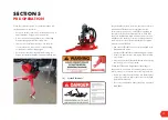
Push - Pull Rod Adjustment
The push – pull rod has 3 points of length adjustment.
• At position (C) is an adjustment to match the boom
arm’s length. If the adjustable boom arm has 3 holes
visible (large yellow circle), then the tie rod needs
3 holes visible (smaller orange circle). At maximum
length, 6 holes are exposed.
• Fine adjustment, primarily to adjust the alignment of
the fans, is via the tie rod ends at each end (D) and (E).
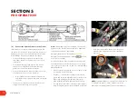
ALWAYS check that the tie rod ends are free to rotate;
The push - pull rod has a bend in order to clear the fan
frame hanger in the parked position - see photo 2 (open)
and photo 3 (parked).
The alignment of the bend is not critical on a 2-row sprayer
(as can be seen in the photo on page 37, position B). The
preferred option is with the bend pointing towards the
direction of travel, as in photo 2.
After making adjustments,
ALWAYS double check
for free movement of the Push-pull rod and connections
throughout the full travel range. Check that the tie rod ends
have free movement.
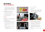
3-Row Boom
3-row sprayers use the “Twin Hanger” system (see G
below) which allows 2 sets of fans to be “hung” onto each
main boom arm. One set of fans face towards the tank (2nd
row), and the other set of fans face towards the “3rd” row.
Each set of fan frames is individually adjustable for spray
direction – normally square to the target (see H &
G below).
Photo 2 shows the Hanger system with boom open and
Photo 3, boom closed.
The Hanger system is also used for Recapture screens, as
shown (see J above).
Fig 3 shows the preferred configuration of a 3-row sprayer
for spraying in 3.0 m rows.
This is the “Standard” build for a 3-row sprayer.
SECTION 5
PRE-OPERATION
C
D
H
G
TRAVEL
Photo 2
J
Photo 3
Figure 3.
Photo 1


