


HT-OMSMART-A
22
SECTION 4
PRODUCT FEATURES / FAMILIARISATION
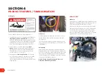
Main Tank Drain
All models have a main tank drain positioned near the step
on the left hand side
(blue circle).
Please dispose of any chemical in a safe and
environmentally responsible manner.
Tank Selection Valve
The tank selection valve has 3 x positions.
1.
SPRAY
- In this position the pump will draw liquid from
the main chemical / product tank.
2.
FLUSH
- In this position the pump will draw freshwater
from the auxiliary flush tank.
3.
OFF
- In this position ALL liquid is isolated from the
pump. It is only recommended to use this position when
pump is not operating i.e. Cleaning out suction filter.
If changing from SPRAY to FLUSH always turn off the pump
before making the change.
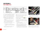
Main Suction Filter
The main suction filter should be checked and cleaned on
a regular basis.
Before opening the filter body, ensure the pump is not
running & the Tank Selection Valve is in the OFF position.
To be safe, always assume there is chemical present and
take the appropriate safety measures.
Always wear gloves.
Sight Gauges
All main tanks are fitted with both a front (RH side) and
side (LH Side) sight gauges. Inside of each clear sight
hose is a white float which can be read against the tank
markings to display the approximate volume remaining in
the tank.
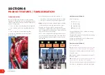
PUMP & PRESSURE PLUMBING
On the pressure output side of the AR pump flow goes to
1. Pressure Manifold where the maximum required
pressure is set (central red knob), and 4 flick taps for …
• Suction Probe
• Front Agitator
• Rear Agitator
• Basket / Powder Mix
2. If fitted, Recapture venturi feed line. This hose, which
has an on/ off ball valve (just visible to the left) is then
routed to supply the venturi at the rear of the sprayer.
3. Servo Dump & Filter manifold which includes
a. Dump valve (fast acting – identified by blue band)
b. Pressure regulating valve (slow acting (15 seconds)
– identified by grey band (visible below 3b)
c. Pressure filter (and includes a pressure sensor that
couples into the fusion loom)
d. To the flow meter (mounted behind the pump)
and then to the spray sections valves at the rear
of the sprayer.
Refer to Section 5 for more information on how
to operate these functions.


