2.12 Connecting Data Devices
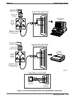
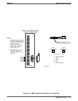
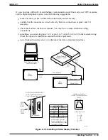
This section contains information on two stages of wiring connections for data devices.
Section 2.12.1 explains connections from stations to modular jacks. Section 2.12.2 details wiring
from the modular jack to the DSU by way of the punch-down-block.
2.12.1
Making Modular Jack Data Connections
Modular jack connections are wiring connections from a station to a modular (wall) jack.
The system provides two RS232 Data Ports for use.
•
When you use a video display terminal (VDT) to perform class of service programming,
connect it to RS232 Data Port A.
•
When you use a serial data printer for SMDR, SMDA, COS printout, or Caller ID, connect
it to the RS232 Data Port B.
NOTE: The distance between a data device and the common equipment can be up to 500 feet
in a quiet electrical environment. Some sites may require shielded cable for long
runs. For longer distances, you must install limited distance modems to relay the data
communications between the common equipment and a data device.
When preparing a cable for connection to a data device, refer to the manufacturer’s manual for
the equipment being interfaced and make the following wiring connections:
•
Wire the common equipment RD (data from device to common equipment) connection to
the device TD (transmit data) connection.
•
Wire the common equipment TD (data to device from common equipment) connection to
the device RD (receive data) connection.
•
Wire the common equipment SG (signal ground) connection to the device SG (signal
ground) connection.
•
If required for proper operation, wire the common equipment CTS (clear-to-send status
from device to common equipment) connection to the device RTS (request-to-send)
connection.
NOTE: The common equipment requires a positive voltage, with respect to signal ground, in
order to send data.
Digital Telephone System
IMI66–107
2 – 34 Installing The DSU
Содержание Air Impact DSU
Страница 2: ...Printed in U S A GCA47 157 ...
Страница 30: ......
Страница 85: ...Figure 2 26 Installing The Batteries batt1 cdr IMI66 107 Digital Telephone System Installing The DSU 2 55 ...
Страница 91: ...Figure 2 28 Detailing The ATI D Dimensions IMI66 107 Digital Telephone System Installing The DSU 2 61 ...
Страница 112: ......
Страница 192: ...Digital Telephone System IMI66 107 3 80 System Programming ...
Страница 283: ......
Страница 284: ......
Страница 285: ......
Страница 286: ......
Страница 287: ......
Страница 288: ......
Страница 289: ......
Страница 290: ......
Страница 291: ......
Страница 292: ......
Страница 293: ......
Страница 294: ......
Страница 295: ......
Страница 296: ......
Страница 297: ......
Страница 298: ......
Страница 299: ......
Страница 300: ......
Страница 301: ......
Страница 302: ......
Страница 303: ......
Страница 304: ......
Страница 305: ......
Страница 306: ......
Страница 307: ......
Страница 308: ......
Страница 309: ......
Страница 310: ......
Страница 311: ......
Страница 312: ......
Страница 313: ......
Страница 314: ......
Страница 315: ......
Страница 316: ......
Страница 317: ......
Страница 318: ......
Страница 319: ......
Страница 320: ......
Страница 321: ......
Страница 322: ......
Страница 323: ......
Страница 324: ......
Страница 325: ......
Страница 326: ......
Страница 327: ......
Страница 328: ......
Страница 329: ......
Страница 330: ......
Страница 331: ......
Страница 332: ......
Страница 333: ......
Страница 334: ......
Страница 335: ......
Страница 336: ......
Страница 337: ......
Страница 338: ......
Страница 339: ......
Страница 340: ......
Страница 431: ......
Страница 436: ......
Страница 437: ......
Страница 438: ......


