2.9
Common Audible And Auxiliary Ringing Interface
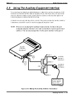
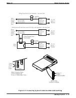
You can use the relay closure dry-contact points for controlling external audible equipment.
These contact closures track the pattern of the ringing for incoming calls. The contacts are closed
during the ringing period and are open during the silent period.
CAUTION
Do not exceed a 1 amp at 24 volts (0.5 amp at 48 volts) load on these control terminals. If the
load requirements exceed this limit, connect the load through an external slave relay. DO
NOT CONNECT THESE CONTROL TERMINALS DIRECTLY TO THE 117VAC LINE.
2.9.1
Connecting Outside Lines
Common audible terminals provide a dry-contact closure whenever any of the outside lines that
you have connected to the common equipment ring with an incoming call.
2.9.2
Connecting Selected Ports
Station 17 audible terminals provide a dry-contact relay closure whenever ringing is sent to
station 17 or to a programmable destination. Use class of service programming to choose either
the station 17 or the programmable paging port as the ringing destination. Refer to Chapter 3 for
programming details.
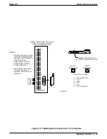
When you have programmed for station port 17 ringing, it is a common practice to use a
customer-supplied external device to provide loud ringing and connected in a manner similar to
the common audible arrangement shown in the illustration on the next page.
CAUTION
Do not connect an external paging device or any external ringing device to station port 17
connections.
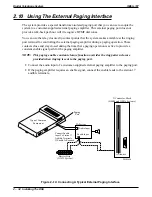
When you have programmed for paging port ringing, it is a common practice to use a
customer-supplied external paging amplifier connected to the paging port to amplify and
broadcast the ringing tones sent to the paging port by the system. You can employ the relay
closures that appear at the ringing terminals to energize the external paging amplifier during the
periods when the ringing tones are being sent if necessary.
NOTE: Refer to Section 2.10 for a discussion of external paging amplifier connections and
information for using the paging port ringing terminals in an alternate paging enable
function.
Digital Telephone System
IMI66–107
2 – 30 Installing The DSU
Содержание Air Impact DSU
Страница 2: ...Printed in U S A GCA47 157 ...
Страница 30: ......
Страница 85: ...Figure 2 26 Installing The Batteries batt1 cdr IMI66 107 Digital Telephone System Installing The DSU 2 55 ...
Страница 91: ...Figure 2 28 Detailing The ATI D Dimensions IMI66 107 Digital Telephone System Installing The DSU 2 61 ...
Страница 112: ......
Страница 192: ...Digital Telephone System IMI66 107 3 80 System Programming ...
Страница 283: ......
Страница 284: ......
Страница 285: ......
Страница 286: ......
Страница 287: ......
Страница 288: ......
Страница 289: ......
Страница 290: ......
Страница 291: ......
Страница 292: ......
Страница 293: ......
Страница 294: ......
Страница 295: ......
Страница 296: ......
Страница 297: ......
Страница 298: ......
Страница 299: ......
Страница 300: ......
Страница 301: ......
Страница 302: ......
Страница 303: ......
Страница 304: ......
Страница 305: ......
Страница 306: ......
Страница 307: ......
Страница 308: ......
Страница 309: ......
Страница 310: ......
Страница 311: ......
Страница 312: ......
Страница 313: ......
Страница 314: ......
Страница 315: ......
Страница 316: ......
Страница 317: ......
Страница 318: ......
Страница 319: ......
Страница 320: ......
Страница 321: ......
Страница 322: ......
Страница 323: ......
Страница 324: ......
Страница 325: ......
Страница 326: ......
Страница 327: ......
Страница 328: ......
Страница 329: ......
Страница 330: ......
Страница 331: ......
Страница 332: ......
Страница 333: ......
Страница 334: ......
Страница 335: ......
Страница 336: ......
Страница 337: ......
Страница 338: ......
Страница 339: ......
Страница 340: ......
Страница 431: ......
Страница 436: ......
Страница 437: ......
Страница 438: ......

