


Chapter 2 — Burner Operation and Control
2-16
Part No. 750-184
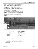
through baffles and filters in the tank before the air passes to the
burner.
Some of the primary air is also used to assist the oil pressure
regulators of the fuel oil controller.
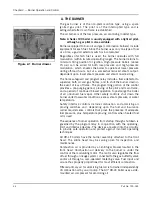
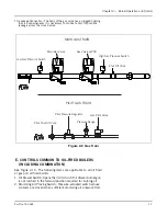
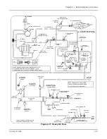
K. OIL FUEL FLOW - LIGHT OIL
The oil fuel flow system schematic is shown in Figure 2-16. Oil flow
is indicated by arrows and the pertinent controls are called out. Fuel
oil is delivered into the system by a supply pump which delivers part
of its discharge to the oil burner. Excess oil is returned to the oil
storage tank through the fuel oil relief valve and oil return line.
Normally the pump operates only while the burner is in operation,
although a positioning switch is often provided so that either
continuous or automatic pump operation can be obtained.
The oil flows through a fuel oil strainer to prevent any foreign
material from flowing through the control valves and nozzle. The
fuel oil controller contains in a single unit, a metering valve, a
regulator, and a gauge required to regulate the pressure and flow of
oil to the burner. The adjustable regulator controls the pressure. To
assist in the regulation, back pressure is created by an orifice nozzle
located in the oil return line immediately downstream of the fuel oil
controller.
The programming relay energizes or deenergizes the solenoid oil
valves to permit or cut off oil flow to the burner. Two valves,
operating simultaneously, are used. The valves are closed when
deenergized. They cannot be opened (energized) unless the
combustion air proving switch and the atomizing air proving switch
are closed. The two switches are satisfied, respectively, by sufficient
combustion air pressure from the forced draft fan and pressurized
air from the air pump.
The oil flow to the burner is controlled by the movement of the
metering stem in the oil metering valve, which varies the flow to
meet load demands. The metering valve and the air damper are
controlled simultaneously at all times by the modulating motor to
proportion combustion air and fuel for changes in load demand.
Содержание CB Ohio Special 100 HP
Страница 2: ...ii ...
Страница 8: ...viii ...
Страница 42: ...Chapter 2 Burner Operation and Control 2 22 Part No 750 184 ...
Страница 116: ...Chapter 6 Adjustment Procedures 6 28 Part No 750 184 ...
Страница 126: ...Chapter 8 Inspection and Maintenance 8 6 Part No 750 184 ...
Страница 153: ...Chapter 9 Parts Part No 750 184 9 3 Insulated Front Head Model CB LE ...
Страница 154: ...Chapter 9 Parts 9 4 Part No 750 184 Insulated Front Head Interior Model CB LE ...
Страница 155: ...Chapter 9 Parts Part No 750 184 9 5 Insulated Inner Door Model CB OS ...
Страница 156: ...Chapter 9 Parts 9 6 Part No 750 184 Insulated Rear Head CB LE ...
Страница 157: ...Chapter 9 Parts Part No 750 184 9 7 Insulated Rear Head CB LE ...
Страница 158: ...Chapter 9 Parts 9 8 Part No 750 184 Insulated Rear Head CB OS ...
Страница 159: ...Chapter 9 Parts Part No 750 184 9 9 Dry Oven Model CB LE ...
Страница 161: ...Chapter 9 Parts Part No 750 184 9 11 Motor Impeller Model CB LE ...
Страница 162: ...Chapter 9 Parts 9 12 Part No 750 184 Front Head Linkage ...
Страница 170: ...Chapter 9 Parts 9 20 Part No 750 184 Control Cabinet Hawk ICS ...
Страница 171: ...Chapter 9 Parts Part No 750 184 9 21 Control Panel Standard ...
Страница 172: ...Chapter 9 Parts 9 22 Part No 750 184 Entrance Box ...
Страница 173: ...Chapter 9 Parts Part No 750 184 9 23 Front Head Electrical CB LE ...
Страница 174: ...Chapter 9 Parts 9 24 Part No 750 184 Front Head Electrical CB LE ...
Страница 175: ...Chapter 9 Parts Part No 750 184 9 25 Front Head Electrical CB OS ...
Страница 176: ...Chapter 9 Parts 9 26 Part No 750 184 Front Head Electrical CB OS ...
Страница 179: ...Chapter 9 Parts Part No 750 184 9 29 Heavy Oil Piping 60 Steam CB LE ...
Страница 180: ...Chapter 9 Parts 9 30 Part No 750 184 Heavy Oil Piping 60 Steam CB LE SEE TABLE NEXT PAGE ...
Страница 181: ...Chapter 9 Parts Part No 750 184 9 31 Common Oil Parts Heavy Oil ...
Страница 182: ...Chapter 9 Parts 9 32 Part No 750 184 Side Mounted Air Compressor Piping ...
Страница 183: ...Chapter 9 Parts Part No 750 184 9 33 Air Compressor Piping CB OS ...
Страница 185: ...Chapter 9 Parts Part No 750 184 9 35 Light Oil Piping ...
Страница 186: ...Chapter 9 Parts 9 36 Part No 750 184 Light Oil Air Piping Front Head ...
Страница 187: ...Chapter 9 Parts Part No 750 184 9 37 Light Oil Air Piping Front Head PAGE 9 31 ...
Страница 191: ...Chapter 9 Parts Part No 750 184 9 41 Gas Train 125 150 HP ...
Страница 193: ...Chapter 9 Parts Part No 750 184 9 43 Gas Train 200 HP ...
Страница 195: ...Chapter 9 Parts Part No 750 184 9 45 Steam Pressure Controls ...
Страница 196: ...Chapter 9 Parts 9 46 Part No 750 184 Hot Water Temperature Controls ...
Страница 197: ...Chapter 9 Parts Part No 750 184 9 47 Water Column ...
Страница 198: ...Chapter 9 Parts 9 48 Part No 750 184 Water Column ...
Страница 199: ...Chapter 9 Parts Part No 750 184 9 49 Fireside Gaskets CB LE ...
Страница 200: ...Chapter 9 Parts 9 50 Part No 750 184 Fireside Gaskets CB OS ...


