


Chapter 2 — Burner Operation and Control
Part No. 750-184
2-15
amount of air for correct ratio of air to fuel for efficient combustion
at all firing rates.
I. AUTOMATIC IGNITION
Oil or gas burners are ignited by an interrupted-type pilot. The pilot
flame is ignited automatically by an electric spark.
The series 100 burner usually is equipped with a pilot fired with
light oil fuel. All other burners are equipped with a gas burning pilot.
In the case of a combination burner, the gas pilot is used to ignite
either the main gas flame or the oil flame. Either pilot serves the
same function. Unless exception is taken in the text, the term pilot
is used interchangeably.
At the beginning of the ignition cycle, and governed by the program
relay, the pilot solenoid valve and ignition transformer are
simultaneously energized.
The ignition transformer supplies high voltage current for the
igniting spark. A gas pilot has a single electrode and a spark arcs
between the tip of the electrode and the wall of the tube surrounding
it. A light oil pilot has two electrodes and the arc is between their
tips. The pilot solenoid valve and the transformer are deenergized
after main flame is ignited and established.
Fuel for the gas pilot is supplied from the utility’s main, or from a
tank (bottle) supply. Secondary air flows into and mixes with the
pilot gas stream to provide an adequate flame.
Insurance regulations may require two gas pilot solenoid valves with
a normally open vent valve between them. The vent valve closes
when the gas pilot valves open, and opens when the gas pilot valves
shut to vent gas, should any be present in the pilot line during the
deenergized period of the gas pilot valves.
Fuel for a light-oil pilot is provided from the line that supplies oil
under pressure for the main flame. A solenoid actuated valve
controls flow of oil to the pilot nozzle. The valve is energized
simultaneously with the ignition transformer at the beginning of the
ignition cycle and is deenergized after main flame is ignited and
established.
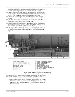
J. ATOMIZING AIR
Air for atomizing the fuel oil (often referred to as “primary air”) is
pumped by the air pump into the air-oil receiver tank and delivered
under pressure through a manifold block to the oil burner nozzle.
The atomizing air mixes with the fuel oil just prior to the oil leaving
the nozzle.
Atomizing air pressure is indicated by the air pressure gauge on the
burner gun.
Air pressure from the pump also forces sufficient oil from the tank
to the pump bearings to lubricate them and also to provide a seal
and lubrication for the pump vanes. As a result, the air delivered to
the tank contains some lube oil; however, most of it is recovered
Содержание CB Ohio Special 100 HP
Страница 2: ...ii ...
Страница 8: ...viii ...
Страница 42: ...Chapter 2 Burner Operation and Control 2 22 Part No 750 184 ...
Страница 116: ...Chapter 6 Adjustment Procedures 6 28 Part No 750 184 ...
Страница 126: ...Chapter 8 Inspection and Maintenance 8 6 Part No 750 184 ...
Страница 153: ...Chapter 9 Parts Part No 750 184 9 3 Insulated Front Head Model CB LE ...
Страница 154: ...Chapter 9 Parts 9 4 Part No 750 184 Insulated Front Head Interior Model CB LE ...
Страница 155: ...Chapter 9 Parts Part No 750 184 9 5 Insulated Inner Door Model CB OS ...
Страница 156: ...Chapter 9 Parts 9 6 Part No 750 184 Insulated Rear Head CB LE ...
Страница 157: ...Chapter 9 Parts Part No 750 184 9 7 Insulated Rear Head CB LE ...
Страница 158: ...Chapter 9 Parts 9 8 Part No 750 184 Insulated Rear Head CB OS ...
Страница 159: ...Chapter 9 Parts Part No 750 184 9 9 Dry Oven Model CB LE ...
Страница 161: ...Chapter 9 Parts Part No 750 184 9 11 Motor Impeller Model CB LE ...
Страница 162: ...Chapter 9 Parts 9 12 Part No 750 184 Front Head Linkage ...
Страница 170: ...Chapter 9 Parts 9 20 Part No 750 184 Control Cabinet Hawk ICS ...
Страница 171: ...Chapter 9 Parts Part No 750 184 9 21 Control Panel Standard ...
Страница 172: ...Chapter 9 Parts 9 22 Part No 750 184 Entrance Box ...
Страница 173: ...Chapter 9 Parts Part No 750 184 9 23 Front Head Electrical CB LE ...
Страница 174: ...Chapter 9 Parts 9 24 Part No 750 184 Front Head Electrical CB LE ...
Страница 175: ...Chapter 9 Parts Part No 750 184 9 25 Front Head Electrical CB OS ...
Страница 176: ...Chapter 9 Parts 9 26 Part No 750 184 Front Head Electrical CB OS ...
Страница 179: ...Chapter 9 Parts Part No 750 184 9 29 Heavy Oil Piping 60 Steam CB LE ...
Страница 180: ...Chapter 9 Parts 9 30 Part No 750 184 Heavy Oil Piping 60 Steam CB LE SEE TABLE NEXT PAGE ...
Страница 181: ...Chapter 9 Parts Part No 750 184 9 31 Common Oil Parts Heavy Oil ...
Страница 182: ...Chapter 9 Parts 9 32 Part No 750 184 Side Mounted Air Compressor Piping ...
Страница 183: ...Chapter 9 Parts Part No 750 184 9 33 Air Compressor Piping CB OS ...
Страница 185: ...Chapter 9 Parts Part No 750 184 9 35 Light Oil Piping ...
Страница 186: ...Chapter 9 Parts 9 36 Part No 750 184 Light Oil Air Piping Front Head ...
Страница 187: ...Chapter 9 Parts Part No 750 184 9 37 Light Oil Air Piping Front Head PAGE 9 31 ...
Страница 191: ...Chapter 9 Parts Part No 750 184 9 41 Gas Train 125 150 HP ...
Страница 193: ...Chapter 9 Parts Part No 750 184 9 43 Gas Train 200 HP ...
Страница 195: ...Chapter 9 Parts Part No 750 184 9 45 Steam Pressure Controls ...
Страница 196: ...Chapter 9 Parts 9 46 Part No 750 184 Hot Water Temperature Controls ...
Страница 197: ...Chapter 9 Parts Part No 750 184 9 47 Water Column ...
Страница 198: ...Chapter 9 Parts 9 48 Part No 750 184 Water Column ...
Страница 199: ...Chapter 9 Parts Part No 750 184 9 49 Fireside Gaskets CB LE ...
Страница 200: ...Chapter 9 Parts 9 50 Part No 750 184 Fireside Gaskets CB OS ...


