


Chapter 6 — Adjustment Procedures
Part No. 750-184
6-5
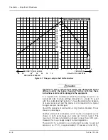
the modulating motor) is set to make red and blue tracer leads at
approximately 60
°
the on motor opening. Normally the settings are
left as is, but job conditions may require readjustment. If the cams
require adjustment or resetting, follow the instructions in the
manufacturer’s technical manual.
E. BURNER OPERATING CONTROLS - GENERAL
Note: Adjustments to the boiler operating controls should be
made by an authorized Cleaver-Brooks Representative.
R e f e r t o t h e a p p r o p r i a t e b o i l e r O p e r a t i o n a n d
Maintenance manual for specific information on boiler
startup and operation.
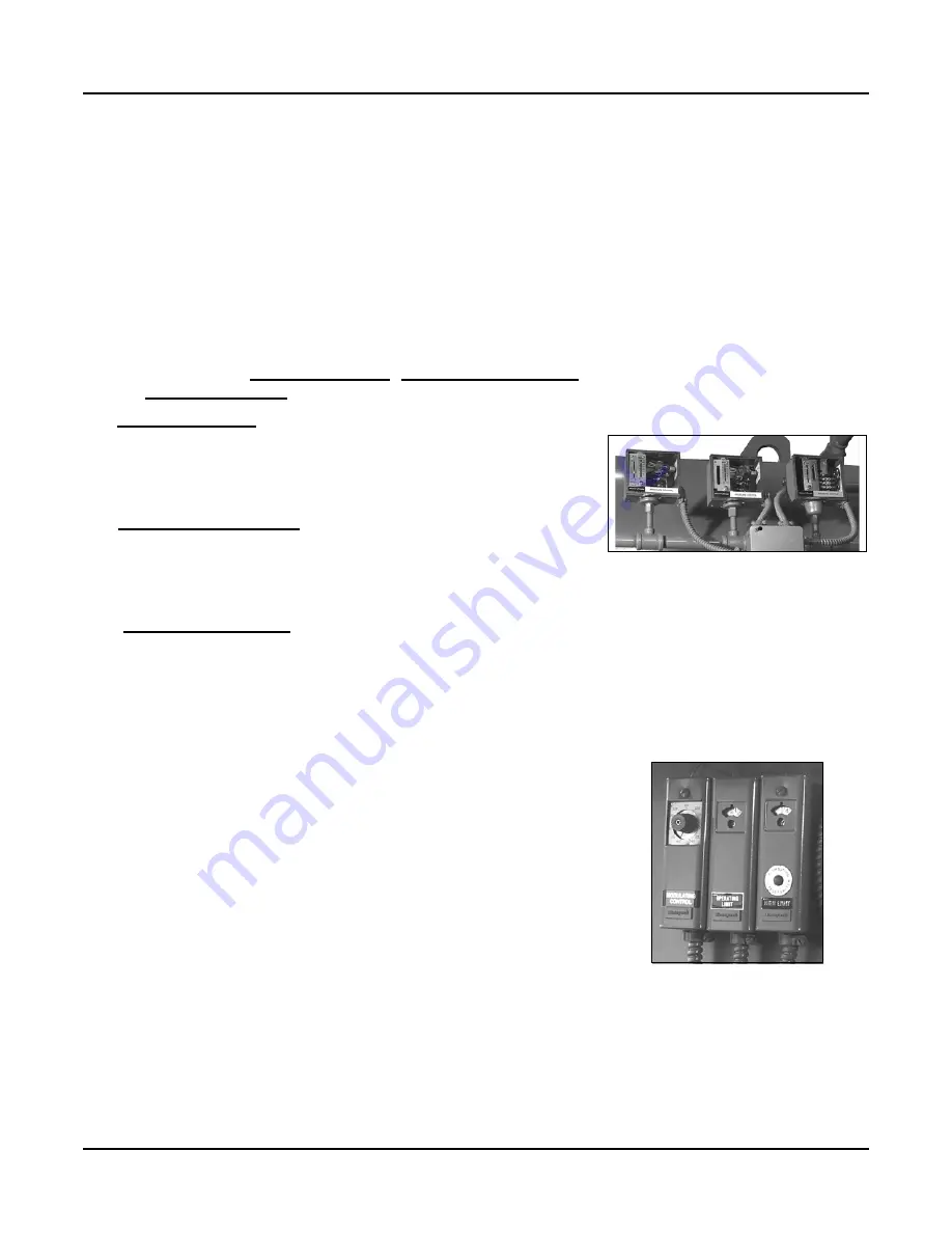
The standard boiler operating control package consists of three
separate controls, the
High Limit Control, Operating Limit Control
and the
Modulating control.
The
High Limit Control
senses the hot water temperature or steam
pressure. It is used as a safety limit to turn the burner off in the
event the operating limit control fails. The high limit control should
be set sufficiently above the operating limit control to avoid
nuisance shutdowns.
The
Operating Limit Control
senses temperature or pressure and
automatically turns the burner on to initiate the start up sequence
when required and turns the burner off to initiate the shutdown
sequence when the demand is satisfied. The control must be set to
initiate startup only at the low fire position.
The
Modulating Control
senses changes in the hot water
temperature or steam pressure and signals the modulating motor to
control the flow of fuel and air to the burner. With either steam or
hot water boilers, the modulating control must be set to ensure the
burner is at its minimum low fire position before the operating limit
control either starts or stops the burner.
When adjusting or setting controls, first be sure all control devices
are securely mounted and level. With the temperature sensing
control, make sure the sensing bulb is properly bottomed in its well
and is secured against movement. Be sure the connecting tubing is
not kinked.
The dial settings are generally accurate, although it is not unusual
to have a slight variation between a scale setting and an actual
pressure gauge or thermometer reading. Always adjust control
setting to agree with pressure gauge or thermometer readings.
Accurate instrument readings are required.
When necessary use
auxiliary test equipment to set controls.
Burner controls correctly set to match load demands will provide
operational advantages and achieve the following desirable
objectives:
• The burner will be operating in low fire position prior to shut
down.
• The burner will operate at low fire for a brief period on each start
during normal operation.
Figure 6-4 Steam Operating Controls
Figure 6-5 Hot Water Controls
Содержание CB Ohio Special 100 HP
Страница 2: ...ii ...
Страница 8: ...viii ...
Страница 42: ...Chapter 2 Burner Operation and Control 2 22 Part No 750 184 ...
Страница 116: ...Chapter 6 Adjustment Procedures 6 28 Part No 750 184 ...
Страница 126: ...Chapter 8 Inspection and Maintenance 8 6 Part No 750 184 ...
Страница 153: ...Chapter 9 Parts Part No 750 184 9 3 Insulated Front Head Model CB LE ...
Страница 154: ...Chapter 9 Parts 9 4 Part No 750 184 Insulated Front Head Interior Model CB LE ...
Страница 155: ...Chapter 9 Parts Part No 750 184 9 5 Insulated Inner Door Model CB OS ...
Страница 156: ...Chapter 9 Parts 9 6 Part No 750 184 Insulated Rear Head CB LE ...
Страница 157: ...Chapter 9 Parts Part No 750 184 9 7 Insulated Rear Head CB LE ...
Страница 158: ...Chapter 9 Parts 9 8 Part No 750 184 Insulated Rear Head CB OS ...
Страница 159: ...Chapter 9 Parts Part No 750 184 9 9 Dry Oven Model CB LE ...
Страница 161: ...Chapter 9 Parts Part No 750 184 9 11 Motor Impeller Model CB LE ...
Страница 162: ...Chapter 9 Parts 9 12 Part No 750 184 Front Head Linkage ...
Страница 170: ...Chapter 9 Parts 9 20 Part No 750 184 Control Cabinet Hawk ICS ...
Страница 171: ...Chapter 9 Parts Part No 750 184 9 21 Control Panel Standard ...
Страница 172: ...Chapter 9 Parts 9 22 Part No 750 184 Entrance Box ...
Страница 173: ...Chapter 9 Parts Part No 750 184 9 23 Front Head Electrical CB LE ...
Страница 174: ...Chapter 9 Parts 9 24 Part No 750 184 Front Head Electrical CB LE ...
Страница 175: ...Chapter 9 Parts Part No 750 184 9 25 Front Head Electrical CB OS ...
Страница 176: ...Chapter 9 Parts 9 26 Part No 750 184 Front Head Electrical CB OS ...
Страница 179: ...Chapter 9 Parts Part No 750 184 9 29 Heavy Oil Piping 60 Steam CB LE ...
Страница 180: ...Chapter 9 Parts 9 30 Part No 750 184 Heavy Oil Piping 60 Steam CB LE SEE TABLE NEXT PAGE ...
Страница 181: ...Chapter 9 Parts Part No 750 184 9 31 Common Oil Parts Heavy Oil ...
Страница 182: ...Chapter 9 Parts 9 32 Part No 750 184 Side Mounted Air Compressor Piping ...
Страница 183: ...Chapter 9 Parts Part No 750 184 9 33 Air Compressor Piping CB OS ...
Страница 185: ...Chapter 9 Parts Part No 750 184 9 35 Light Oil Piping ...
Страница 186: ...Chapter 9 Parts 9 36 Part No 750 184 Light Oil Air Piping Front Head ...
Страница 187: ...Chapter 9 Parts Part No 750 184 9 37 Light Oil Air Piping Front Head PAGE 9 31 ...
Страница 191: ...Chapter 9 Parts Part No 750 184 9 41 Gas Train 125 150 HP ...
Страница 193: ...Chapter 9 Parts Part No 750 184 9 43 Gas Train 200 HP ...
Страница 195: ...Chapter 9 Parts Part No 750 184 9 45 Steam Pressure Controls ...
Страница 196: ...Chapter 9 Parts 9 46 Part No 750 184 Hot Water Temperature Controls ...
Страница 197: ...Chapter 9 Parts Part No 750 184 9 47 Water Column ...
Страница 198: ...Chapter 9 Parts 9 48 Part No 750 184 Water Column ...
Страница 199: ...Chapter 9 Parts Part No 750 184 9 49 Fireside Gaskets CB LE ...
Страница 200: ...Chapter 9 Parts 9 50 Part No 750 184 Fireside Gaskets CB OS ...


