


Chapter 2 — Burner Operation and Control
Part No. 750-184
2-5
subsequent setting of fuel input throughout the firing range. It
has no control over the firing rate when the manual-automatic
switch is set on “automatic.”
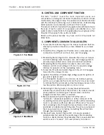
11.Burner Switch (Figure 2-8): A manually operated start-stop
switch for directly starting and stopping operation of burner.
12.Flame Detector: Monitors gas or oil pilot and energizes the
programmer flame relay in response to a flame signal. It
continues to monitor main flame (oil or gas) after expiration of
pilot providing period. A standard equipped boiler has a lead
sulfide (infrared sensitive) detector.
13.Combustion Air Proving Switch: A pressure-sensitive switch
actuated by air pressure from the forced draft fan. Its contacts
close to prove presence of combustion air. The fuel valves cannot
be energized unless this switch is satisfied. The combustion air
proving switch is provided on all gas fired or combination gas-oil
burners. An oil fired boiler does not normally have a separate
switch but utilizes the atomizing air proving switch to the same
effect, since the presence of atomizing air from the air pump,
which is belt driven from the blower motor, is evidence of blower
operation.
14.Alarm: Sounds to notify the operator of a condition requiring
attention. The alarm is available as optional equipment.
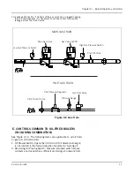
15.Stack Thermometer (Figure 2-6): Indicates temperature of
vented flue gases.
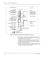
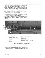
16.Diffuser (Figure 2-7): A circular plate, located at the furnace end
of the burner drawer, that imparts a rotary swirling motion to
combustion air immediately prior to its entering the flame, thus
providing a thorough and efficient mixture with the fuel.
17.Rotary Air Damper (Figure 2-7): Provides accurate control of
combustion air in proportion to fuel input for various load
demands. It consists of two concentric cylinders with openings.
The outer is stationary. The inner is rotated, under control of the
modulating motor, to vary the effective size of the openings
where they overlap.
18.Indicator Lights (Figure 2-8): Provide visual information of boiler
operation as follows (indicator lights vary with controls
provided):
• Flame Failure
• Load Demand
• Fuel Valve (valve open)
• Low Water
Figure 2-6 Stack Thermometer
Figure 2-7 Diffuser & Damper
Diffuser
Rotary Air
Damper
Figure 2-8 Control Panel
Содержание CB Ohio Special 100 HP
Страница 2: ...ii ...
Страница 8: ...viii ...
Страница 42: ...Chapter 2 Burner Operation and Control 2 22 Part No 750 184 ...
Страница 116: ...Chapter 6 Adjustment Procedures 6 28 Part No 750 184 ...
Страница 126: ...Chapter 8 Inspection and Maintenance 8 6 Part No 750 184 ...
Страница 153: ...Chapter 9 Parts Part No 750 184 9 3 Insulated Front Head Model CB LE ...
Страница 154: ...Chapter 9 Parts 9 4 Part No 750 184 Insulated Front Head Interior Model CB LE ...
Страница 155: ...Chapter 9 Parts Part No 750 184 9 5 Insulated Inner Door Model CB OS ...
Страница 156: ...Chapter 9 Parts 9 6 Part No 750 184 Insulated Rear Head CB LE ...
Страница 157: ...Chapter 9 Parts Part No 750 184 9 7 Insulated Rear Head CB LE ...
Страница 158: ...Chapter 9 Parts 9 8 Part No 750 184 Insulated Rear Head CB OS ...
Страница 159: ...Chapter 9 Parts Part No 750 184 9 9 Dry Oven Model CB LE ...
Страница 161: ...Chapter 9 Parts Part No 750 184 9 11 Motor Impeller Model CB LE ...
Страница 162: ...Chapter 9 Parts 9 12 Part No 750 184 Front Head Linkage ...
Страница 170: ...Chapter 9 Parts 9 20 Part No 750 184 Control Cabinet Hawk ICS ...
Страница 171: ...Chapter 9 Parts Part No 750 184 9 21 Control Panel Standard ...
Страница 172: ...Chapter 9 Parts 9 22 Part No 750 184 Entrance Box ...
Страница 173: ...Chapter 9 Parts Part No 750 184 9 23 Front Head Electrical CB LE ...
Страница 174: ...Chapter 9 Parts 9 24 Part No 750 184 Front Head Electrical CB LE ...
Страница 175: ...Chapter 9 Parts Part No 750 184 9 25 Front Head Electrical CB OS ...
Страница 176: ...Chapter 9 Parts 9 26 Part No 750 184 Front Head Electrical CB OS ...
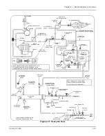
Страница 179: ...Chapter 9 Parts Part No 750 184 9 29 Heavy Oil Piping 60 Steam CB LE ...
Страница 180: ...Chapter 9 Parts 9 30 Part No 750 184 Heavy Oil Piping 60 Steam CB LE SEE TABLE NEXT PAGE ...
Страница 181: ...Chapter 9 Parts Part No 750 184 9 31 Common Oil Parts Heavy Oil ...
Страница 182: ...Chapter 9 Parts 9 32 Part No 750 184 Side Mounted Air Compressor Piping ...
Страница 183: ...Chapter 9 Parts Part No 750 184 9 33 Air Compressor Piping CB OS ...
Страница 185: ...Chapter 9 Parts Part No 750 184 9 35 Light Oil Piping ...
Страница 186: ...Chapter 9 Parts 9 36 Part No 750 184 Light Oil Air Piping Front Head ...
Страница 187: ...Chapter 9 Parts Part No 750 184 9 37 Light Oil Air Piping Front Head PAGE 9 31 ...
Страница 191: ...Chapter 9 Parts Part No 750 184 9 41 Gas Train 125 150 HP ...
Страница 193: ...Chapter 9 Parts Part No 750 184 9 43 Gas Train 200 HP ...
Страница 195: ...Chapter 9 Parts Part No 750 184 9 45 Steam Pressure Controls ...
Страница 196: ...Chapter 9 Parts 9 46 Part No 750 184 Hot Water Temperature Controls ...
Страница 197: ...Chapter 9 Parts Part No 750 184 9 47 Water Column ...
Страница 198: ...Chapter 9 Parts 9 48 Part No 750 184 Water Column ...
Страница 199: ...Chapter 9 Parts Part No 750 184 9 49 Fireside Gaskets CB LE ...
Страница 200: ...Chapter 9 Parts 9 50 Part No 750 184 Fireside Gaskets CB OS ...