


Chapter 6 — Adjustment Procedures
6-4
Part No. 750-184
Burners). In this position, fuel delivery is at low fire rate. Tighten the
set screws to secure the cams on the jackshaft.
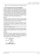
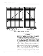
Refer to Figure 6-2. The stop screw in the rotary air damper limits
damper travel at both closed (low fire) and fully opened (high fire)
positions. The screw is provided so that it is possible to tell, even
with the burner is in place, whether the damper rotor is in fully
opened or closed position. Rotating the damper clockwise to the
s t o p s c r e w o p e n s t h e d a m p e r. R o t a t i n g t h e d a m p e r
counterclockwise to the stop screw closes the damper. Normally,
the rate of flow of air through the damper with the rotor in low fire
position is about one-third of maximum for a standard burner.
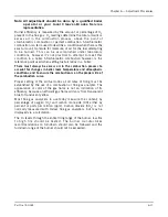
The amount of angular movement controlling the rate of air flow is
determined by the location of the ends of the rotary air damper rod
in both the jack shaft arm and the air damper arm.When the air
damper is in low fire position, the jackshaft arm should be at 45
°
and the rotar y air damper arm should be at an an gle of
approximately 60
°
below the horizontal (Figure 6-1). This will
ensure that the angular movement of the damper starts slowly,
increasing in rate as the high fire position is approached.
Prior to initially firing a boiler it is advisable to check for free
movement of the linkage. The damper motor must be allowed to
complete its full stroke and the damper must move freely from low
to high fire position. Adjustment of linkage connected to a gas
butterfly valve is described in Section Q of Chapter 6.
C. MODULATING MOTOR
The modulating motor has a 90
°
shaft rotation. The motor
manufacturer also provides a 160
°
stroke model for other
applications.
If a replacement is obtained from someone other than
a Cleaver-Brooks Service or Parts representative, it may have an
incorrect stroke. To prevent damage, determine the 90
°
stroke
prior to installing a replacement.
The stroke may be determined by powering the motor and
connecting terminals R-B to actually determine the stroke as motor
drives to an open position.
D. MODULATING MOTOR SWITCHES - LOW FIRE AND
HIGH FIRE
The modulating motor contains either one or two internal switches
depending upon application. The microswitches are actuated by
adjustable cams attached to the motor shaft.
Note: If the boiler is equipped with the CB-Hawk ICS, there are
n o en d s w i t ch e s. D o n ot at t em p t t o a dj u s t t he
Modulating Motor if the unit is equipped with the CB-
Hawk ICS
Factory replacement motors have the cams preset. The low fire start
switch is set to make the red and yellow leads at approximately 8
°
on motor closing. The high fire purge air proving switch (located in
Figure 6-2
JACK SHAFT
ROTARY AIR
DAMPER ARM
ROTARY AIR
DAMPER
STOP SCREW
DIFFUSER PLATE
DAMPER ARM
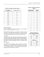
Figure 6-3
1.
ADJUST
THE
LINKAGE
TOWARD
T H E
D R I V E
S H A F T
F O R
L E S S
MOVEMENT
.
2.
ADJUST
AWAY
FROM
THE
DRIVE
S H A F T
F O R
M O R E
L I N K A G E
MOVEMENT
.
1
2
Содержание CB Ohio Special 100 HP
Страница 2: ...ii ...
Страница 8: ...viii ...
Страница 42: ...Chapter 2 Burner Operation and Control 2 22 Part No 750 184 ...
Страница 116: ...Chapter 6 Adjustment Procedures 6 28 Part No 750 184 ...
Страница 126: ...Chapter 8 Inspection and Maintenance 8 6 Part No 750 184 ...
Страница 153: ...Chapter 9 Parts Part No 750 184 9 3 Insulated Front Head Model CB LE ...
Страница 154: ...Chapter 9 Parts 9 4 Part No 750 184 Insulated Front Head Interior Model CB LE ...
Страница 155: ...Chapter 9 Parts Part No 750 184 9 5 Insulated Inner Door Model CB OS ...
Страница 156: ...Chapter 9 Parts 9 6 Part No 750 184 Insulated Rear Head CB LE ...
Страница 157: ...Chapter 9 Parts Part No 750 184 9 7 Insulated Rear Head CB LE ...
Страница 158: ...Chapter 9 Parts 9 8 Part No 750 184 Insulated Rear Head CB OS ...
Страница 159: ...Chapter 9 Parts Part No 750 184 9 9 Dry Oven Model CB LE ...
Страница 161: ...Chapter 9 Parts Part No 750 184 9 11 Motor Impeller Model CB LE ...
Страница 162: ...Chapter 9 Parts 9 12 Part No 750 184 Front Head Linkage ...
Страница 170: ...Chapter 9 Parts 9 20 Part No 750 184 Control Cabinet Hawk ICS ...
Страница 171: ...Chapter 9 Parts Part No 750 184 9 21 Control Panel Standard ...
Страница 172: ...Chapter 9 Parts 9 22 Part No 750 184 Entrance Box ...
Страница 173: ...Chapter 9 Parts Part No 750 184 9 23 Front Head Electrical CB LE ...
Страница 174: ...Chapter 9 Parts 9 24 Part No 750 184 Front Head Electrical CB LE ...
Страница 175: ...Chapter 9 Parts Part No 750 184 9 25 Front Head Electrical CB OS ...
Страница 176: ...Chapter 9 Parts 9 26 Part No 750 184 Front Head Electrical CB OS ...
Страница 179: ...Chapter 9 Parts Part No 750 184 9 29 Heavy Oil Piping 60 Steam CB LE ...
Страница 180: ...Chapter 9 Parts 9 30 Part No 750 184 Heavy Oil Piping 60 Steam CB LE SEE TABLE NEXT PAGE ...
Страница 181: ...Chapter 9 Parts Part No 750 184 9 31 Common Oil Parts Heavy Oil ...
Страница 182: ...Chapter 9 Parts 9 32 Part No 750 184 Side Mounted Air Compressor Piping ...
Страница 183: ...Chapter 9 Parts Part No 750 184 9 33 Air Compressor Piping CB OS ...
Страница 185: ...Chapter 9 Parts Part No 750 184 9 35 Light Oil Piping ...
Страница 186: ...Chapter 9 Parts 9 36 Part No 750 184 Light Oil Air Piping Front Head ...
Страница 187: ...Chapter 9 Parts Part No 750 184 9 37 Light Oil Air Piping Front Head PAGE 9 31 ...
Страница 191: ...Chapter 9 Parts Part No 750 184 9 41 Gas Train 125 150 HP ...
Страница 193: ...Chapter 9 Parts Part No 750 184 9 43 Gas Train 200 HP ...
Страница 195: ...Chapter 9 Parts Part No 750 184 9 45 Steam Pressure Controls ...
Страница 196: ...Chapter 9 Parts 9 46 Part No 750 184 Hot Water Temperature Controls ...
Страница 197: ...Chapter 9 Parts Part No 750 184 9 47 Water Column ...
Страница 198: ...Chapter 9 Parts 9 48 Part No 750 184 Water Column ...
Страница 199: ...Chapter 9 Parts Part No 750 184 9 49 Fireside Gaskets CB LE ...
Страница 200: ...Chapter 9 Parts 9 50 Part No 750 184 Fireside Gaskets CB OS ...