


Chapter 2 — Burner Operation and Control
2-14
Part No. 750-184
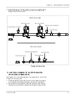
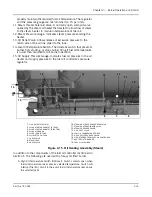
B. Hot Water Oil Heater Thermostat: Used on a hot water boiler to sense
fuel oil temperature and control the starting and stopping of the
booster water pump.
C. Booster Water Pump: Started and stopped by the hot water
thermostat to regulate the flow of hot water through the hot water oil
heater to maintain temperature of fuel oil.
D. Fuel Oil Thermometer: Indicates temperature of fuel oil being
supplied to the fuel oil controller.
E. Back Pressure Valve: For adjustment of oil pressure on the
downstream side of the metering valve. Also regulates rate of return
oil flow.
F. Oil Return Pressure Gauge: Indicates oil pressure on the return side
of the fuel oil controller.
G. Manual By-Pass Valve: Provided as a time saver in establishing oil
flow. When open, it permits circulation of oil through the supply and
return lines. The valve
must
be closed prior to initial light off.
H. Orifice Oil Control Valve: Valve may be opened prior to start-up to aid
in establishing fuel oil flow through the controller. The valve must be
closed prior to initial light off. Its disc has an orifice to permit a
continuous circulation of hot fuel oil through the controller.
I. Air Purge Valve: Solenoid valve opens simultaneously with closing of
oil solenoid valve at burner shutdown, allowing compressed air to
purge oil from the burner nozzle and adjacent piping. The oil is
burned by the diminishing flame, which continues burning for
approximately 4 seconds after the oil solenoid valve closes.
J. Air Purge Orifice Nozzle: Limits purging air to proper quantity for
expelling unburned oil at normal delivery rate.
K. Air Purge Orifice Nozzle Filter: Filters the purging air of any particles
that might plug the air purge orifice nozzle.
L. Air Purge Check Valve: Valve check prevents fuel oil from entering the
atomizing air line.
M.Air Purge Relay: When energized, controls operation of air purge
valve.
G. CONTROLS FOR COMBINATION BURNERS ONLY
Burners equipped to burn either oil or gas include equipment for
each fuel. The selector switch engages the appropriate interlocks
and controls for gas or oil operation.
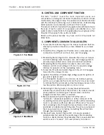
H. COMBUSTION AIR
Air for combustion of fuel (often referred to as “secondary” air) is
furnished by the forced draft fan mounted in the boiler head. In
operation, air pressure is built up in the entire head and is forced
through a diffuser plate for a thorough mixture with the fuel for
proper combustion. The supply of secondary air to the burner is
governed by automatically throttling the output of the fan by
regulating the rotary air damper. The damper provides the proper
Содержание CB Ohio Special 100 HP
Страница 2: ...ii ...
Страница 8: ...viii ...
Страница 42: ...Chapter 2 Burner Operation and Control 2 22 Part No 750 184 ...
Страница 116: ...Chapter 6 Adjustment Procedures 6 28 Part No 750 184 ...
Страница 126: ...Chapter 8 Inspection and Maintenance 8 6 Part No 750 184 ...
Страница 153: ...Chapter 9 Parts Part No 750 184 9 3 Insulated Front Head Model CB LE ...
Страница 154: ...Chapter 9 Parts 9 4 Part No 750 184 Insulated Front Head Interior Model CB LE ...
Страница 155: ...Chapter 9 Parts Part No 750 184 9 5 Insulated Inner Door Model CB OS ...
Страница 156: ...Chapter 9 Parts 9 6 Part No 750 184 Insulated Rear Head CB LE ...
Страница 157: ...Chapter 9 Parts Part No 750 184 9 7 Insulated Rear Head CB LE ...
Страница 158: ...Chapter 9 Parts 9 8 Part No 750 184 Insulated Rear Head CB OS ...
Страница 159: ...Chapter 9 Parts Part No 750 184 9 9 Dry Oven Model CB LE ...
Страница 161: ...Chapter 9 Parts Part No 750 184 9 11 Motor Impeller Model CB LE ...
Страница 162: ...Chapter 9 Parts 9 12 Part No 750 184 Front Head Linkage ...
Страница 170: ...Chapter 9 Parts 9 20 Part No 750 184 Control Cabinet Hawk ICS ...
Страница 171: ...Chapter 9 Parts Part No 750 184 9 21 Control Panel Standard ...
Страница 172: ...Chapter 9 Parts 9 22 Part No 750 184 Entrance Box ...
Страница 173: ...Chapter 9 Parts Part No 750 184 9 23 Front Head Electrical CB LE ...
Страница 174: ...Chapter 9 Parts 9 24 Part No 750 184 Front Head Electrical CB LE ...
Страница 175: ...Chapter 9 Parts Part No 750 184 9 25 Front Head Electrical CB OS ...
Страница 176: ...Chapter 9 Parts 9 26 Part No 750 184 Front Head Electrical CB OS ...
Страница 179: ...Chapter 9 Parts Part No 750 184 9 29 Heavy Oil Piping 60 Steam CB LE ...
Страница 180: ...Chapter 9 Parts 9 30 Part No 750 184 Heavy Oil Piping 60 Steam CB LE SEE TABLE NEXT PAGE ...
Страница 181: ...Chapter 9 Parts Part No 750 184 9 31 Common Oil Parts Heavy Oil ...
Страница 182: ...Chapter 9 Parts 9 32 Part No 750 184 Side Mounted Air Compressor Piping ...
Страница 183: ...Chapter 9 Parts Part No 750 184 9 33 Air Compressor Piping CB OS ...
Страница 185: ...Chapter 9 Parts Part No 750 184 9 35 Light Oil Piping ...
Страница 186: ...Chapter 9 Parts 9 36 Part No 750 184 Light Oil Air Piping Front Head ...
Страница 187: ...Chapter 9 Parts Part No 750 184 9 37 Light Oil Air Piping Front Head PAGE 9 31 ...
Страница 191: ...Chapter 9 Parts Part No 750 184 9 41 Gas Train 125 150 HP ...
Страница 193: ...Chapter 9 Parts Part No 750 184 9 43 Gas Train 200 HP ...
Страница 195: ...Chapter 9 Parts Part No 750 184 9 45 Steam Pressure Controls ...
Страница 196: ...Chapter 9 Parts 9 46 Part No 750 184 Hot Water Temperature Controls ...
Страница 197: ...Chapter 9 Parts Part No 750 184 9 47 Water Column ...
Страница 198: ...Chapter 9 Parts 9 48 Part No 750 184 Water Column ...
Страница 199: ...Chapter 9 Parts Part No 750 184 9 49 Fireside Gaskets CB LE ...
Страница 200: ...Chapter 9 Parts 9 50 Part No 750 184 Fireside Gaskets CB OS ...


