


Chapter 8 — Inspection and Maintenance
Part No. 750-184
8-5
D. WATER GAUGE GLASS
A broken or discolored glass should be replaced at once. Periodic
replacement should be a part of the maintenance program. Always use new
gaskets when replacing a glass. Use a proper size rubber packing. Do not
use loose packing, which could be forced below the glass and possibly plug
the valve opening.
Close the valves when replacing the glass. Slip a packing nut, a packing
washer, and packing ring onto each end of the glass. Insert one end of the
glass into the upper gauge valve body far enough to allow the lower end to
be dropped into the lower body. Slide the packing nuts onto each valve and
tighten.
!
Warning
Do not attempt to change the gauge glass while the boiler is
in service. Failure to follow these instructions could result
in serious personal injury or death.
Check try-cocks and gauge cocks for freedom of operation and clean as
required. It is imperative that the gauge cocks are mounted in exact
alignment. If they are not, the glass will be strained and may fail
prematurely.
E. ELECTRICAL CONTROLS
The operating controls should be inspected monthly. Examine tightness of
electrical connections and keep the controls clean. Remove any dust that
accumulates in the interior of the control using a low pressure air. Take care
not to damage the mechanism.
Examine any mercury tube switches for damage or cracks. Dark scum over
the normally bright surface of the mercury, may lead to erratic switching
action. Be certain that controls are correctly leveled. The piping leading to
the pressure control actuators should be cleaned, if necessary. Covers should
be left on controls at all times.
Dust and dirt can cause excessive wear and overheating of motor starter and
relay contacts. Use a burnishing tool or a hard surface paper to clean and
polish contacts. Starter contacts are plated with silver and are not harmed
by discoloration and slight pitting. Replacement of the contacts is necessary
only if the silver has worn thin.
!
Caution
Do not use files or abrasive materials such as sandpaper on
the contact points. Failure to follow these instructions could
result in equipment damage.
Thermal relay units (overloads) are of the melting-alloy type and, when
tripped, the alloy must be given time to re-solidify before relay can be reset.
If the overloads trip out repeatedly when the motor current is normal, replace
them with new overloads. If the condition continues after replacement, it will
be necessary to determine the cause of excessive current draw at the
overloads.
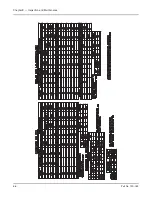
Power supply to the boiler must be protected with dual element fuses
(fusetrons) or circuit breakers. Similar fuses should be used in branch
circuits. Standard one-shot fuses are not recommended. See next page for
fuse sizes.
Содержание CB Ohio Special 100 HP
Страница 2: ...ii ...
Страница 8: ...viii ...
Страница 42: ...Chapter 2 Burner Operation and Control 2 22 Part No 750 184 ...
Страница 116: ...Chapter 6 Adjustment Procedures 6 28 Part No 750 184 ...
Страница 126: ...Chapter 8 Inspection and Maintenance 8 6 Part No 750 184 ...
Страница 153: ...Chapter 9 Parts Part No 750 184 9 3 Insulated Front Head Model CB LE ...
Страница 154: ...Chapter 9 Parts 9 4 Part No 750 184 Insulated Front Head Interior Model CB LE ...
Страница 155: ...Chapter 9 Parts Part No 750 184 9 5 Insulated Inner Door Model CB OS ...
Страница 156: ...Chapter 9 Parts 9 6 Part No 750 184 Insulated Rear Head CB LE ...
Страница 157: ...Chapter 9 Parts Part No 750 184 9 7 Insulated Rear Head CB LE ...
Страница 158: ...Chapter 9 Parts 9 8 Part No 750 184 Insulated Rear Head CB OS ...
Страница 159: ...Chapter 9 Parts Part No 750 184 9 9 Dry Oven Model CB LE ...
Страница 161: ...Chapter 9 Parts Part No 750 184 9 11 Motor Impeller Model CB LE ...
Страница 162: ...Chapter 9 Parts 9 12 Part No 750 184 Front Head Linkage ...
Страница 170: ...Chapter 9 Parts 9 20 Part No 750 184 Control Cabinet Hawk ICS ...
Страница 171: ...Chapter 9 Parts Part No 750 184 9 21 Control Panel Standard ...
Страница 172: ...Chapter 9 Parts 9 22 Part No 750 184 Entrance Box ...
Страница 173: ...Chapter 9 Parts Part No 750 184 9 23 Front Head Electrical CB LE ...
Страница 174: ...Chapter 9 Parts 9 24 Part No 750 184 Front Head Electrical CB LE ...
Страница 175: ...Chapter 9 Parts Part No 750 184 9 25 Front Head Electrical CB OS ...
Страница 176: ...Chapter 9 Parts 9 26 Part No 750 184 Front Head Electrical CB OS ...
Страница 179: ...Chapter 9 Parts Part No 750 184 9 29 Heavy Oil Piping 60 Steam CB LE ...
Страница 180: ...Chapter 9 Parts 9 30 Part No 750 184 Heavy Oil Piping 60 Steam CB LE SEE TABLE NEXT PAGE ...
Страница 181: ...Chapter 9 Parts Part No 750 184 9 31 Common Oil Parts Heavy Oil ...
Страница 182: ...Chapter 9 Parts 9 32 Part No 750 184 Side Mounted Air Compressor Piping ...
Страница 183: ...Chapter 9 Parts Part No 750 184 9 33 Air Compressor Piping CB OS ...
Страница 185: ...Chapter 9 Parts Part No 750 184 9 35 Light Oil Piping ...
Страница 186: ...Chapter 9 Parts 9 36 Part No 750 184 Light Oil Air Piping Front Head ...
Страница 187: ...Chapter 9 Parts Part No 750 184 9 37 Light Oil Air Piping Front Head PAGE 9 31 ...
Страница 191: ...Chapter 9 Parts Part No 750 184 9 41 Gas Train 125 150 HP ...
Страница 193: ...Chapter 9 Parts Part No 750 184 9 43 Gas Train 200 HP ...
Страница 195: ...Chapter 9 Parts Part No 750 184 9 45 Steam Pressure Controls ...
Страница 196: ...Chapter 9 Parts 9 46 Part No 750 184 Hot Water Temperature Controls ...
Страница 197: ...Chapter 9 Parts Part No 750 184 9 47 Water Column ...
Страница 198: ...Chapter 9 Parts 9 48 Part No 750 184 Water Column ...
Страница 199: ...Chapter 9 Parts Part No 750 184 9 49 Fireside Gaskets CB LE ...
Страница 200: ...Chapter 9 Parts 9 50 Part No 750 184 Fireside Gaskets CB OS ...


