


Chapter 6 — Adjustment Procedures
6-20
Part No. 750-184
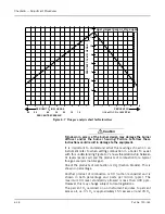
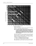
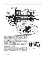
Since the input of combustion air is ordinarily fixed at any given
point in the modulating cycle, the flue gas reading is determined by
varying the input of gas fuel at that setting. The adjustment is made
to the metering cam by means of adjusting screws, which are turned
outward (counterclockwise from the hex-socket end) to increase the
flow of fuel, and inward (clockwise from the hex-socket end) to
decrease it. Flow rate is highest when the cam follower assembly is
closest to jackshaft.
Through the manual flame control switch, position the cam so that
the adjusting screw adjacent to the end or high fire screw contacts
the cam follower. Perform a combustion analysis at this point. If an
adjustment is necessary, turn the adjustment screw accordingly to
increase or decrease fuel flow. Take a combustion reading to verify
input. Repeat as necessary until the desired flow is obtained.
Repeat the process, stopping at each adjusting screw, until the low
fire adjusting screw is reached.
Note: Do not use any lubricant on the adjusting setscrews.
The set screws have a nylon locking insert intended to
provide locking torque and resistance to loosening and
a lubricant could damage equipment.
Standard Burner Low Fire Adjustment
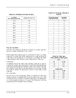
The fuel input should be adjusted using the low fire cam screw, to
approximately 25% of that at high fire (Table 6-6). At low fire the
O
2
flue gas reading should be between 6-7%.
It may be necessary to readjust the setting of the low fire stop screw
to obtain the proper air/fuel ratio at the low fire rate. To ensure that
the low fire position of the gas butterfly valve is always the same,
allow one turn of the stop screw for overtravel.
If the air damper needs to be adjusted in order to provide the correct
low fire air/fuel ratio, combustion must be rechecked at higher firing
rates and adjusted as required.
If all cam screws are properly adjusted, none will deviate from the
general overall contour of the cam face.
R. LOW-GAS-PRESSURE SWITCH
Adjust the scale setting to slightly below the normal burning
pressure. The control circuit will be broken when pressure falls
below this point. Since gas line distribution pressure may decrease
under some conditions, shutdowns may result if the setting is too
close to normal. However, regulations require that the setting may
not be less than 50% of the rated pressure downstream of the
regulator.
Manual resetting is necessary after a pressure drop
. Press the reset
lever after pressure is restored. Be sure that the mercury switch
equipped control is level.
Содержание CB Ohio Special 100 HP
Страница 2: ...ii ...
Страница 8: ...viii ...
Страница 42: ...Chapter 2 Burner Operation and Control 2 22 Part No 750 184 ...
Страница 116: ...Chapter 6 Adjustment Procedures 6 28 Part No 750 184 ...
Страница 126: ...Chapter 8 Inspection and Maintenance 8 6 Part No 750 184 ...
Страница 153: ...Chapter 9 Parts Part No 750 184 9 3 Insulated Front Head Model CB LE ...
Страница 154: ...Chapter 9 Parts 9 4 Part No 750 184 Insulated Front Head Interior Model CB LE ...
Страница 155: ...Chapter 9 Parts Part No 750 184 9 5 Insulated Inner Door Model CB OS ...
Страница 156: ...Chapter 9 Parts 9 6 Part No 750 184 Insulated Rear Head CB LE ...
Страница 157: ...Chapter 9 Parts Part No 750 184 9 7 Insulated Rear Head CB LE ...
Страница 158: ...Chapter 9 Parts 9 8 Part No 750 184 Insulated Rear Head CB OS ...
Страница 159: ...Chapter 9 Parts Part No 750 184 9 9 Dry Oven Model CB LE ...
Страница 161: ...Chapter 9 Parts Part No 750 184 9 11 Motor Impeller Model CB LE ...
Страница 162: ...Chapter 9 Parts 9 12 Part No 750 184 Front Head Linkage ...
Страница 170: ...Chapter 9 Parts 9 20 Part No 750 184 Control Cabinet Hawk ICS ...
Страница 171: ...Chapter 9 Parts Part No 750 184 9 21 Control Panel Standard ...
Страница 172: ...Chapter 9 Parts 9 22 Part No 750 184 Entrance Box ...
Страница 173: ...Chapter 9 Parts Part No 750 184 9 23 Front Head Electrical CB LE ...
Страница 174: ...Chapter 9 Parts 9 24 Part No 750 184 Front Head Electrical CB LE ...
Страница 175: ...Chapter 9 Parts Part No 750 184 9 25 Front Head Electrical CB OS ...
Страница 176: ...Chapter 9 Parts 9 26 Part No 750 184 Front Head Electrical CB OS ...
Страница 179: ...Chapter 9 Parts Part No 750 184 9 29 Heavy Oil Piping 60 Steam CB LE ...
Страница 180: ...Chapter 9 Parts 9 30 Part No 750 184 Heavy Oil Piping 60 Steam CB LE SEE TABLE NEXT PAGE ...
Страница 181: ...Chapter 9 Parts Part No 750 184 9 31 Common Oil Parts Heavy Oil ...
Страница 182: ...Chapter 9 Parts 9 32 Part No 750 184 Side Mounted Air Compressor Piping ...
Страница 183: ...Chapter 9 Parts Part No 750 184 9 33 Air Compressor Piping CB OS ...
Страница 185: ...Chapter 9 Parts Part No 750 184 9 35 Light Oil Piping ...
Страница 186: ...Chapter 9 Parts 9 36 Part No 750 184 Light Oil Air Piping Front Head ...
Страница 187: ...Chapter 9 Parts Part No 750 184 9 37 Light Oil Air Piping Front Head PAGE 9 31 ...
Страница 191: ...Chapter 9 Parts Part No 750 184 9 41 Gas Train 125 150 HP ...
Страница 193: ...Chapter 9 Parts Part No 750 184 9 43 Gas Train 200 HP ...
Страница 195: ...Chapter 9 Parts Part No 750 184 9 45 Steam Pressure Controls ...
Страница 196: ...Chapter 9 Parts 9 46 Part No 750 184 Hot Water Temperature Controls ...
Страница 197: ...Chapter 9 Parts Part No 750 184 9 47 Water Column ...
Страница 198: ...Chapter 9 Parts 9 48 Part No 750 184 Water Column ...
Страница 199: ...Chapter 9 Parts Part No 750 184 9 49 Fireside Gaskets CB LE ...
Страница 200: ...Chapter 9 Parts 9 50 Part No 750 184 Fireside Gaskets CB OS ...


